As an Amazon Associate, Akermin earns from qualifying purchases. Product links on this page are affiliate links.
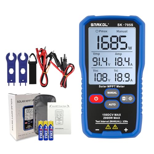
Fienzio · Solar MPPT Power Tester for Photovoltaic Modules, 2000 W, 150 V DC Max, 45 A, Automatic & Manual Power Measurement, Voc Isc Vmp Pmax, 3.2" LCD with Backlight, Portable PV Tester (SK-705S)
View on AmazonPrice and availability are shown on Amazon and can change at any time.
A portable photovoltaic module tester that measures Pmax, Vmp, Imp, Voc and Isc, with automatic and manual modes, a 3.2 inch backlit LCD with data hold, a rear hanging slot, and test leads and clips supplied. The measurement set is the right one for commissioning and fault finding. The problem is that the listing states two different maximum voltages, 150 V in the product name and 80 V in the specification bullet, and on a solar tester that figure is a safety limit.
The contradiction, and why it is not a detail
Set the two statements side by side.
| Where | Maximum power | Maximum voltage | Current |
|---|---|---|---|
| Product name | 2000 W | 150 V DC | 45 A |
| Specification bullet | 1000 W | 80 V DC | 0 to 45 A |
The power rating differs by a factor of two and the voltage ceiling by nearly a factor of two. Only the current agrees. These are not two ways of saying the same thing, and nothing in the listing reconciles them.
On most instruments a contradictory specification is an irritation. Here it is different, because the voltage ceiling is the limit that keeps the instrument and its user intact.
A photovoltaic array is a source you cannot turn off. In daylight it sits at its open circuit voltage, and it is there before you connect anything and still there afterwards. If the real ceiling is 80 V and you connect it across a string resting at 120 V, the instrument is outside its rating from the moment the second clip lands.
The margin is thinner than it looks, too. Open circuit voltage rises as cell temperature falls, so a cold clear morning pushes a string above its nameplate figure, which is exactly when commissioning tends to happen. Anyone sizing an instrument to a string works from the cold weather figure, not the nameplate.
So the honest position is this: we cannot tell you whether this tester is good for 80 V or 150 V, and the listing gives you no way to decide. Establish it with the manufacturer before connecting it to anything, and size your decision on the lower figure until you have an answer in writing.
The measurement set is the right one
Leaving the ratings aside, what the instrument measures is well chosen. The listing states Pmax, Vmp, Imp, Voc and Isc.
Those five figures are how you tell a working module from a failing one.
- Voc, open circuit voltage, is what the panel produces with nothing drawing from it. A low Voc points at a cell or a bypass diode problem.
- Isc, short circuit current, is what it delivers into a dead short. It tracks irradiance closely, so it tells you whether the panel is receiving the light you think it is.
- Pmax is the most power the panel can actually deliver, which is the number that matters commercially.
- Vmp and Imp are the voltage and current at that maximum power point. Their ratio tells you where on the curve the panel peaks, which shifts when cells degrade.
Measured together and compared against the module datasheet, corrected for the irradiance and temperature at the time, that is a performance verdict. Our guide on measuring solar panel output covers why the correction matters and how much a reading moves without it.
What this is not
The product name calls it an MPPT power tester, and the first bullet describes MPPT power measurement. That wording invites a misunderstanding worth clearing up.
This instrument finds a panel maximum power point in order to measure it. It is not an MPPT charge controller and it does not replace one, and it does not test whether your charge controller is tracking correctly. It characterises the module.
It is also not a full I-V curve tracer, although it measures the points a curve would pass through. A tracer sweeps the load from open circuit to short circuit and draws the whole relationship, and the shape of that line is diagnostic: a step reveals a shaded or mismatched sub string, a rounded knee suggests series resistance. Reading five key values tells you whether performance is acceptable. Reading the curve tells you why it is not.
For most installation and maintenance checks the five values are sufficient and faster. For investigating an underperforming string, a tracer is the better instrument.
The practical details
| Specification | Published in the listing |
|---|---|
| Measurements | Pmax, Vmp, Imp, Voc, Isc |
| Modes | Automatic continuous, manual single test |
| Display | 3.2 inch LCD, backlit, data hold |
| Current range | 0 to 45 A, consistent in both statements |
| Maximum voltage | Contradictory, 150 V in the name and 80 V in the bullets |
| Maximum power | Contradictory, 2000 W in the name and 1000 W in the bullets |
| Supplied | Test leads, alligator clips, pouch, manual |
| Physical | Compact, lightweight, rear hanging slot |
| Measurement accuracy | Not stated in the listing bullets |
| Irradiance or temperature input | Not stated in the listing bullets |
| Data logging or export | Not stated in the listing bullets |
Two of the practical touches are better than they look. Data hold freezes a reading, which matters when the instrument is clipped to a string on a roof and you are not in a position to read it at the moment of measurement. The rear hanging slot is the same thinking: both hands are usually occupied.
The absent accuracy figure is a real gap for commissioning work, where the point of the exercise is to record a number someone may rely on later. And with no irradiance or temperature input, any comparison against a datasheet has to be corrected using figures you measure separately.
The verdict
The measurement set, the two modes and the practical design all suit module level performance checking, and alligator clips with a pouch means it is ready to use. As a tool for confirming that panels are delivering close to nameplate, this is a sensible class of instrument.
We cannot recommend buying it on this listing. Not because the instrument is necessarily poor, but because the single most safety relevant specification appears twice with two different values, and the lower of the two, 80 V, would exclude a great many residential strings. Resolve the voltage rating with the seller first. If the answer is 80 V, size accordingly. If the answer is 150 V, the listing needs correcting, and you should have that answer in writing before you clip onto anything in daylight.
Recommended Tools
Products shown because their documented specifications fit this guide. Price and availability are on Amazon and can change.
Frequently Asked Questions
What exactly is the contradiction?
The product name states 2000 W, 150 V DC Max, 45 A. The second bullet states support for up to 1000 W output power, 80 V DC maximum voltage and 0 to 45 A current. Those are two different power ratings and two different voltage ceilings for the same instrument. Only the current figure agrees. We cannot tell you which is correct, and that is the problem.
Why does the voltage ceiling matter so much?
Because it is a safety limit on a circuit that cannot be switched off. A PV string in daylight produces its open circuit voltage whether you are ready or not, and connecting an instrument rated for 80 V to a string sitting at 120 V risks damaging it and injuring you. On cold bright days open circuit voltage rises above the nameplate figure, so the margin matters. This is not a specification to guess at.
What does the instrument actually measure?
The listing states Pmax, Vmp, Imp, Voc and Isc. Voc is open circuit voltage and Isc is short circuit current, the two endpoints of a panel behaviour. Pmax is the maximum power the panel can deliver, with Vmp and Imp the voltage and current at that point. Together they tell you whether a module is performing near its nameplate or has degraded.
Is this the same as an I-V curve tracer?
Not quite. A curve tracer sweeps the whole current and voltage relationship and draws the shape, which reveals faults like mismatch and shading steps. This measures the key points on that curve rather than plotting it. For a pass or fail performance check that is usually enough. For diagnosing why a string underperforms, a full curve tells you more.
What do auto and manual modes do?
The listing describes automatic mode for continuous measurements and manual mode for controlled single tests. Continuous is for watching a panel as conditions change or as you shade part of it deliberately. Single test is for commissioning, where you want one recorded figure per module under stated conditions.
Affiliate disclosure: Akermin earns a commission from qualifying Amazon purchases made through links on this page. Our editorial picks are based on documented specifications and owner feedback, not commissions.