As an Amazon Associate, Akermin earns from qualifying purchases. Product links on this page are affiliate links.
For most electricians working on live three-phase equipment, P1 is the pick because it is the only tester here that the listing describes as non-contact and certified to CAT III 600V, which is the combination that matters when you are checking rotation at a panel you cannot isolate. P2 is the practical alternative if you want clip-on connections and a published 75 to 1000VAC input range, and P4 is the choice when the job is specifically confirming motor rotation direction before coupling a load. P3 publishes an operating frequency range of 20 Hz to 400 Hz and a 2000V protection level, but the listing is thin on the contact method and safety category, so treat it as a budget option whose exact measurement conditions you should confirm before relying on it.
Why phase sequence is a safety check, not a convenience check
Three-phase power arrives as three sine waves separated by 120 degrees. The order in which they peak is the phase sequence, and it is either clockwise or counter-clockwise depending on how the supply is wired. A three-phase motor connected to a clockwise sequence turns one way; connect the same motor to a counter-clockwise sequence and it turns the other way. For a pump, that can mean no flow or a dry run. For a compressor, it can mean the wrong direction of rotation and a mechanical fault. For a drive or a piece of equipment with a phase-monitoring relay, it can mean a trip or a refusal to start.
What makes phase sequence testing different from most electrical measurements is that there is no single conductor to measure. The instrument has to compare the timing relationship between three phases, which is why a phase sequence tester is not a multimeter with a different label. A multimeter can tell you each phase is present and roughly what voltage it carries. It cannot tell you the order. That is the whole point of the instrument, and it is why the two families here, non-contact rotation meters and clip-on rotation testers, exist.
The second difference is that you often want to make this check before energizing equipment, but you may also need to make it on a live panel where isolation is not practical. That is where the contact method and the safety category stop being paperwork and start being the reason you choose one instrument over another. A non-contact rotation meter lets you check sequence without metallic contact with the conductors, which reduces the exposure. A clip-on tester requires you to attach to the conductors, which is fine when you can do it safely and awkward when the terminals are crowded.
What the four listings publish, side by side
The table below uses only what the manufacturer listings state. Where a listing is silent, the cell says Not stated. This is deliberate: a phase sequence tester’s published voltage range, frequency range and safety category are the numbers that tell you whether it suits your supply, and a missing number is information too.
| Specification | P1 Hioki PD3129 | P2 Extech PRT200 | P3 ATOPLEE | P4 Ideal 61-521 |
|---|---|---|---|---|
| Measurement method | Non-contact, non-metallic contact points | Non-contact, insulated alligator clips | Not stated | Clip-on, color-coded alligator clips |
| Voltage range | Not stated in the listing bullets | 75 to 1000VAC | Limit support voltage 2000 V/min | Not stated in the listing bullets |
| Frequency range | Not stated in the listing bullets | 45 to 65Hz | 20 Hz to 400 Hz | Not stated in the listing bullets |
| Safety category | CAT III 600V, CE Mark | Not stated in the listing bullets | Protection level 2000 V, impulse 4000 V | Not stated in the listing bullets |
| Indication | Phase rotation | LEDs for orientation and live phase | LED and buzzer | Phase sequence, motor rotation, open phase |
| Lead length | Not stated in the listing bullets | Not stated in the listing bullets | Approx. 1 m (3.3 ft) | Not stated in the listing bullets |
The note that matters: P1 is the only listing here that pairs a non-contact method with a published CAT III 600V rating. P2 publishes the widest clear voltage window, 75 to 1000VAC, but does not state a safety category. P3 publishes the widest frequency range and a protection level, but does not state the contact method. P4 is the only listing that explicitly names motor rotation direction and open phase detection as functions. None of the four listings publishes an accuracy figure for the phase angle measurement, which is a real gap if you need to know how close to 120 degrees the phases actually are.
The four phase sequence testers compared
Hioki PD3129 Phase and Rotation Meter
The only tester here whose listing states non-contact phase rotation measurement and a CAT III 600V certified design, which together let you check rotation without metallic contact on a live panel. The listing calls it a non-contact phase rotation meter with non-metallic contact points and the highest primary supply level safety class rating specifically for phase detectors. If you work on energized three-phase distribution and want the measurement to happen without touching conductors, this is the pick the listing supports.
Extech PRT200 Non-Contact Phase Sequence Tester
The listing publishes a 75 to 1000VAC input voltage range and a 45 to 65Hz frequency range, which covers standard 50Hz and 60Hz three-phase supplies. LEDs indicate phase orientation, clockwise or counter-clockwise, and whether each phase is live, and the connection is fully insulated alligator clips with wide jaws. That combination makes it a straightforward clip-on rotation checker for the voltages most commercial and light industrial work involves.
ATOPLEE 3 Phase Sequence Presence Rotation Tester
The listing publishes a 20 Hz to 400 Hz operating frequency range, a 2000 V/min limit support voltage, a 2000V protection level with 4000V impulse voltage, and test leads of approximately 1 meter. The wide frequency range is unusual among the group and may suit variable frequency or generator work, but the listing does not state a safety category or a contact method, so the exact measurement conditions are less clear than for P1 and P2.
Ideal Electrical 3-Phase Motor Rotation Tester
The listing frames this tester around motor rotation direction, open phase detection and color-coded alligator clips. That is a different emphasis from the rotation meters above: it is aimed at confirming which way a motor will turn and whether a phase is missing, rather than at general phase sequence checking at a panel. If your job is commissioning a motor before it is coupled to a load, the listing describes exactly that workflow.
Non-contact or clip-on: the choice is about access, not accuracy
The two families do the same job by different means. A non-contact rotation meter senses the electric field around each conductor and compares the sequence in which the fields peak. A clip-on tester makes galvanic connection to each phase through alligator clips and compares the voltage waveforms directly. In principle the clip-on method gives the instrument a cleaner signal, but in practice both methods identify sequence reliably when the conductors are within the instrument’s published voltage and frequency window.
The decision is therefore about access and exposure. If the conductors are behind an enclosure, in a crowded terminal block, or at a panel you cannot isolate, a non-contact meter such as P1 lets you hold the instrument near the conductors and read the rotation without attaching anything. If the conductors are exposed and you can clip on safely, P2 and P4 give you a positive connection that will not drift as you move the instrument. P3’s listing does not state the contact method, so you cannot tell from the bullets alone which family it belongs to; that is a question to resolve before buying.
One more practical point: the clip-on testers here use alligator clips with wide jaws (P2) or color-coded clips (P4). Wide jaws matter when the terminals are large or the conductors are thick. Color coding matters when you are working in a panel where mis-clipping a phase is the error you are trying to avoid. Neither is a substitute for checking the sequence indication against a known-good supply before you trust the instrument on a job.
The specification the listings do not publish, and why you should ask
Phase sequence is a timing measurement, but none of these four listings publishes a phase angle accuracy or a resolution. What they publish is the presence of an indication: clockwise or counter-clockwise, live or not live, sequence correct or not. That is enough for the common task of confirming that a supply is in the expected order before connecting a motor. It is not enough if your job requires you to verify that the phase separation is close to 120 degrees, because a sequence tester indicates order, not balance.
If you need to know the actual phase angles, the right instrument is a three-phase power analyzer, not a sequence tester. A sequence tester tells you the order is A-B-C. It does not tell you the voltages are equal or the angles are exactly 120 degrees apart. For motor rotation and panel commissioning, order is usually the question. For power quality investigation, it is not, and you should reach for a different class of instrument. The three-phase power analyzers comparison covers that side of the job.
The other gap is the safety category. Only P1 publishes one, CAT III 600V. P3 publishes a protection level of 2000 V and an impulse voltage of 4000 V, which describes the instrument’s withstand capability but is not the same as a measurement category rating. P2 and P4 do not publish a category at all. If you are working on a fixed installation where the available fault current is high, the category rating is the number that tells you the instrument is rated for that location. Where the listing is silent, ask the manufacturer before you rely on the instrument at the service entrance.
Where a phase sequence tester stops being the right instrument
A phase sequence tester confirms order. It does not confirm that a motor is safe to run, that insulation is sound, or that a circuit is de-energized. If your job is to prove a circuit is dead before you touch it, the correct tool is a voltage tester used according to a live-dead-live procedure, and the voltage testers comparison covers that. A sequence tester is not an alarm and not a substitute for lockout.
If your job is to check a motor’s insulation resistance before energizing it, the sequence tester will not help. That is an insulation resistance tester’s task, covered in the insulation resistance testers comparison. Sequence testing sits alongside those checks in a commissioning sequence: prove dead, prove insulation, confirm sequence, then energize. Skipping the sequence check because the supply looked right is how motors end up running backwards.
There is also a limit at the low end. A non-contact rotation meter senses electric fields, and at very low voltages the field may be too weak to detect reliably. P2 publishes a lower limit of 75VAC, which is a useful number because it tells you the instrument is not intended for low-voltage control circuits. P1 does not publish a voltage range in its bullets, so if you need to check a low-voltage three-phase control supply, confirm the lower limit before buying. P3’s 20 Hz to 400 Hz range suggests it is aimed at a wider set of supplies, but the listing does not state a minimum voltage, so the same caution applies.
Recommended Tools


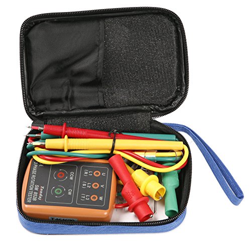

Products shown because their documented specifications fit this guide. Price and availability are on Amazon and can change.
Frequently Asked Questions
Can I use a multimeter to check phase sequence?
No. A multimeter measures voltage, current and resistance between two points. Phase sequence is a timing relationship between three phases, and a two-probe multimeter cannot compare three waveforms in the way a sequence tester does. Some multifunction testers include a phase rotation function, but the instrument has to be designed for it. A multimeter can tell you each phase is present and roughly what voltage it carries, which is a different check.
Do I need a non-contact tester or a clip-on tester?
It depends on access and exposure. If the conductors are exposed and you can clip on safely, a clip-on tester such as P2 or P4 gives a positive connection. If the conductors are behind an enclosure or in a crowded panel you cannot isolate, a non-contact meter such as P1 lets you check rotation without attaching anything. The listing for P3 does not state the contact method, so confirm that before buying if the method matters to your workflow.
What does the safety category rating actually mean on a phase sequence tester?
A measurement category rating, such as CAT III 600V, describes the transient overvoltage environment the instrument is rated to withstand. CAT III covers distribution-level circuits, including panelboards and fixed wiring. Only P1 publishes a category rating among these four, CAT III 600V. P3 publishes a protection level of 2000 V and an impulse voltage of 4000 V, which is a withstand specification rather than a category. P2 and P4 do not publish a category, so if you are working at a service entrance, ask the manufacturer before relying on them there.
Can a phase sequence tester tell me if the phases are balanced?
No. A sequence tester indicates order, clockwise or counter-clockwise, and in some models whether each phase is live. It does not measure the voltage on each phase or the angle between them, so it cannot tell you whether the supply is balanced. If balance matters, you need a three-phase power analyzer or a three-phase clamp meter with power quality functions. The sequence tester answers a narrower question: is the order correct.
What does open phase detection add on P4?
The P4 listing states that it detects missing or open phases. In practice this means that if one of the three phases is absent, the tester indicates that condition rather than simply failing to show a sequence. That is useful during commissioning because a missing phase can look like a wiring error when it is actually a blown fuse or a loose connection upstream. The listing also states that it confirms motor rotation direction, which is the function most directly aimed at preventing a motor from being coupled to a load and running backwards.
What is the frequency range for, and does it matter?
The frequency range tells you which supplies the tester is designed to read. P2 publishes 45 to 65Hz, which covers standard 50Hz and 60Hz mains. P3 publishes 20 Hz to 400 Hz, which is wider and may suit variable frequency drive outputs or generator supplies at non-standard frequencies. P1 and P4 do not publish a frequency range in their bullets. If your supply is not standard mains frequency, the published range is the number to check first, because a tester designed for 50/60Hz may not indicate correctly outside that window.
Affiliate disclosure: Akermin earns a commission from qualifying Amazon purchases made through links on this page. Our editorial picks are based on documented specifications and owner feedback, not commissions.