As an Amazon Associate, Akermin earns from qualifying purchases. Product links on this page are affiliate links.
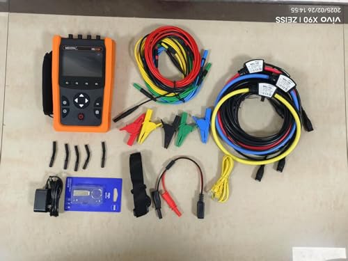
Short answer: For most industrial troubleshooting, P3 and P4 are the same instrument with different current clamps, and either is the strongest all-round choice here: four voltage and four current channels, harmonics to the 50th order, THD, phasor diagrams, transient capture and inrush recording. If you need flexible coils for large or awkward busbars, P5 adds IEC 61010 CAT IV 600V / CAT III 1000V safety ratings and short-term flicker. If you mainly need long-term logging of power, power factor and energy rather than deep harmonic analysis, P11 is the simpler tool. If budget is the constraint, P8 covers the core power quantities and THD with a smaller feature set. A clamp meter remains useful for quick current checks, but it cannot show you phase angle, harmonic spectrum or unbalance.
What a clamp meter cannot tell you about a three phase load
A clamp meter answers one question well: how much current is flowing in this conductor right now. That is a useful answer, and for checking a motor is drawing roughly what its nameplate suggests, it is often enough. It stops being enough the moment the problem is not about magnitude.
Three phase power is a relationship between three voltages and three currents, each with a magnitude and a phase angle. Power factor is the cosine of the angle between a phase voltage and its current. Unbalance is the departure of the three phase magnitudes and angles from their ideal 120 degree spacing. Harmonics are the frequency components above the fundamental that make the current waveform non-sinusoidal. None of these are visible on a single current reading.
The practical consequence is that a clamp meter can show a feeder carrying its rated current while missing that the current is 30 percent harmonic content, that the neutral is carrying more than any phase, or that one phase is 15 degrees out from where it should be. Those are the conditions that overheat transformers, trip drives and shorten motor life. A three phase analyzer measures all channels together and calculates the relationships, which is why it exists as a separate instrument class. For quick single-conductor checks, a clamp meter remains the right tool; for the system view, it is not.
Harmonics, THD and why the 50th order matters
A harmonic is a component of the current or voltage waveform at an integer multiple of the fundamental frequency. On a 50Hz supply, the 3rd harmonic is 150Hz, the 5th is 250Hz, and the 50th is 2500Hz. Non-linear loads, meaning drives, rectifiers, switch mode power supplies and arc equipment, draw current in short pulses rather than smooth sine waves, and those pulses contain a wide spread of harmonic frequencies.
THD, total harmonic distortion, is a single number summarising how much harmonic content is present relative to the fundamental. It is useful as a headline but it does not tell you which harmonic is causing the problem. The 5th and 7th harmonics produce negative and positive sequence components that oppose or assist motor rotation. The triplen harmonics, 3rd, 9th, 15th and so on, add in the neutral. To act on a distortion problem you need the individual harmonic magnitudes, which is why analyzers display a harmonic histogram or spectrum rather than only a THD figure.
The order limit matters because the energy in a distorted current does not stop at low frequencies. A drive with a fast switching front end can have significant content well above the 25th order. An analyzer that stops at the 25th order will understate the total distortion and miss the components most likely to cause additional heating in transformers and cables. The instruments here that state harmonics up to the 50th order, P3, P4, P5 and P7, cover the band that matters for typical industrial non-linear loads. P8 states THD but does not publish the maximum order, so its spectrum depth cannot be confirmed from the listing.
Power factor, displacement and the difference from distortion
Power factor is real power divided by apparent power. On a purely sinusoidal system it equals the cosine of the angle between voltage and current, which is why it is often called displacement power factor. A lagging current from an inductive motor gives a low power factor and draws more current than the real power alone would require, which is why utilities and plant engineers correct it with capacitors.
On a distorted system the relationship breaks down. True power factor includes both the displacement angle and the distortion caused by harmonics. An instrument that only calculates displacement power factor from the fundamental will report a healthy number while the true power factor, and the current actually flowing, is worse. This is why a phasor diagram and a harmonic spectrum together give a fuller picture than a single power factor reading.
The instruments here differ in how they present this. P3, P4 and P5 state phasor diagram display alongside harmonic analysis, so both the angle and the distortion are visible. P1 states power factor measurement from -1.000 to 1.000, covering leading and lagging, but does not state harmonic analysis, so its power factor is best treated as a displacement figure. P8 states active, reactive and apparent power by phase and cumulative, which allows true power factor to be calculated from the ratio, plus transformer K factor for harmonic heating assessment.
Unbalance, neutral current and the fourth channel
Voltage unbalance is the difference between the three phase voltage magnitudes and their departure from 120 degree spacing. Its effect on a motor is disproportionate: a 2 percent voltage unbalance can produce a current unbalance several times larger, because the negative sequence component sees a low impedance in the motor. The result is rotor heating and reduced insulation life, often with no obvious symptom until the motor fails.
Neutral current is the other half of the unbalance story. In a balanced linear system the three phase currents sum to zero at the neutral and no current flows. In a system with triplen harmonics the harmonic currents sum rather than cancel, and the neutral carries current even when the phases are balanced. On a modern office or plant floor full of switch mode loads, this is common, and it is invisible to a three phase, three channel instrument.
This is the argument for four current channels. P3, P4 and P5 all state four voltage and four current channels, which allows the neutral to be measured directly. P8 states four voltage and current channels. P1 does not state the channel count. P2 does not state it either. If your investigation involves a hot neutral or a suspected unbalance, confirm the channel count before buying, because inferring neutral current from three phase readings assumes the system is linear, which is exactly the assumption that fails when harmonics are present.
Where a three phase analyzer stops being the right answer
A three phase power analyzer is a diagnostic instrument, not a protection device. It will not trip a breaker, alarm on a fault or disconnect a load. If you need continuous protection against overcurrent, earth fault or arc flash, that is a different product class, and no analyzer here substitutes for it. Similarly, an analyzer is not a billing meter: where accuracy is not published in the listing, as is the case for several instruments here, its readings support diagnosis but not commercial settlement.
There are also jobs where the analyzer is simply the wrong size. Fault finding on a single motor branch circuit, checking a control panel or verifying a sensor loop is faster with a multimeter or a clamp meter than with a four channel analyzer that needs six connections and a setup routine. A three phase analyzer earns its place when the problem is systemic: a whole distribution board, a feeder, a transformer, a machine with a drive on it.
Finally, consider the adjacent instruments. If the concern is whether a panel is overheating rather than whether its waveform is distorted, a thermal camera for electrical inspection answers that question directly and faster. If the concern is capturing a long-term energy profile rather than a fast transient, a dedicated power quality logger may be simpler and cheaper than a full analyzer. Buy the analyzer when you need the waveform, the spectrum and the phase relationships together. Buy something else when you do not.