As an Amazon Associate, Akermin earns from qualifying purchases. Product links on this page are affiliate links.
A Rogowski coil is a helical winding on a flexible non magnetic former, wrapped around a conductor so that it links the magnetic field the current produces. Because there is no iron, the voltage it generates is proportional to the rate of change of that current rather than to the current itself, and an integrator in the instrument reconstructs the waveform. Those two facts set both limits. Nothing can saturate, so the upper range runs into thousands of amps with no loss of linearity. A steady direct current has no rate of change, so the coil produces nothing and no amount of electronics can recover a measurement that was never generated.
A coil with no iron in it responds to the rate of change
Picture a long, thin solenoid wound evenly along a flexible tube, with one lead brought back through the middle of that tube to the starting end. Bend the tube into a circle around a cable and clip the two ends together. The winding now follows a closed path that encircles the conductor, and the return lead through the centre cancels the single large turn that the loop would otherwise form, which is what stops the whole assembly behaving like a one turn pickup for stray fields.
The magnetic field around a conductor circles it, and its strength integrated around any closed path depends only on the current enclosed by that path. Each small section of the winding sees the component of that field along the tube, and the whole coil therefore links a flux proportional to the enclosed current. Induction converts a changing linked flux into a voltage, and the constant relating the two is the mutual inductance, set by the turns per unit length and the cross sectional area of the winding.
The important consequence hides in the word changing. The output is proportional to how fast the current changes, not to how large it is. Air has a constant permeability at any field strength, so that relationship stays perfectly linear whether the enclosed current is a few amps or several thousand. There is no hysteresis, no remanent magnetism and no point at which the response curves over.
The integrator is the instrument, and it is why direct current vanishes
A voltage proportional to rate of change is not yet a current reading. To recover the current, the instrument integrates that voltage over time, either with an analogue stage built around an operational amplifier and a capacitor, or digitally after sampling. The integrator is where most of the engineering lives and where most of the error comes from, which is why two probes built on identical coils can perform very differently.
An integrator has one unavoidable weakness. Any small constant offset at its input is accumulated indefinitely, so the output wanders away without bound unless something resets it. Practical designs therefore roll off the response at low frequency, which caps the wander at the cost of making the probe deaf to slow changes. At zero frequency, where the current is simply steady, two things coincide: the coil generates nothing and the integrator deliberately ignores what it would have generated.
That is why a flexible probe measures alternating current only, even on an instrument whose other functions handle direct current comfortably. The ETCR6920B flexible coil clamp meter makes the split visible in its own specification: it states alternating current measurement from zero milliamps up to ten thousand amps through the coil, and voltage measurement up to seven hundred and fifty volts alternating and one thousand volts direct through the leads, alongside resistance to two kilohms and a continuity test. Direct current appears on the voltage side and never on the coil side, which is the physics rather than a feature omission.
No core means no saturation, which is where the ten thousand amps comes from
An iron cored clamp works by concentrating flux in a magnetic circuit, which is what gives it a usable signal at low current. Iron has a finite capacity for flux. Past a certain field strength the core saturates, the relationship between current and flux flattens, and the instrument under reads while distorting the waveform. Manufacturers size the core for the intended range, which is why a clamp rated for a few hundred amps is physically larger than one rated for tens.
Remove the core and that ceiling disappears. Linearity in an air cored coil is limited by the electronics, not by any magnetic material, so the same physical loop can cover an enormous span. The range quoted on the flexible meter above runs from milliamps to five figures of amps on one scale, and a coil of three hundred millimetres diameter will go round a conductor that no rigid jaw could approach. The practical trade is at the bottom of the range rather than the top, because the small mutual inductance makes the low current signal weak.
Waveform fidelity is the other benefit. A core that saturates on the peaks of a distorted waveform clips exactly the part a harmonic measurement cares about, while an air cored loop stays linear through peaks and transients. For anyone relating current to power, that fidelity is the difference between a usable figure and a misleading one, and the relationship between the quantities is set out in our explainer on watts, volts and amps.
Return path geometry and the error you can introduce by hand
In theory the output depends only on the enclosed current and not at all on where inside the loop the conductor sits, nor on conductors outside it. That result follows from the field integral around a closed path, and it is the reason a flexible probe can be thrown around an awkward bundle without careful positioning. In practice the theory assumes a perfectly uniform winding on a perfectly closed path, and real coils fall short in one specific place.
The clasp is that place. Where the two ends meet there is a short section with no winding, or with a different winding density, and the cancellation is imperfect there. A conductor pressed against the clasp produces the largest positional error the probe is capable of, and a strong adjacent current passing close to the clasp is the most likely source of external interference. Keeping the conductor near the centre of the loop and rotating the clasp away from both the conductor and its neighbours removes most of the practical error.
Two further habits matter. Keep the loop roughly circular rather than pulled into a flat oval, since a deformed loop changes the effective area along its length. And remember what is being measured is the net enclosed current, so a loop that accidentally encircles a return conductor as well will report the difference between them, which is usually close to zero and occasionally reported as a faulty probe.
Three ways to read current without breaking the circuit
| Method | Physical principle | Direct current | Behaviour at high current | Main practical limit |
|---|---|---|---|---|
| Rogowski coil | Induction in an air cored winding, then integration | No response at all | Stays linear, no saturation | Weak signal and integrator wander at low current |
| Iron cored transformer clamp | Flux concentrated in a split magnetic core | No response at all | Saturates above the design range and under reads | Core size sets the range, jaws must close round the conductor |
| Hall effect clamp | Voltage across a semiconductor in the gap of a core | Reads direct current | Core still saturates, and the element has a ceiling | Offset drift with temperature, needs zeroing before each use |
The table explains why a toolbag often contains two of them. A Hall effect clamp is the only one of the three that answers a direct current question, and it pays for that with an offset that has to be nulled every time the instrument is switched on. An iron cored clamp is the strongest performer at small alternating currents, where a flexible loop struggles. The flexible loop wins on access, on range and on waveform fidelity, which is a specific combination rather than a general superiority, and our overview of clamp meters with flexible current probes covers the instruments built around it.
Choosing a flexible loop and knowing what it leaves to other instruments
Judge a flexible probe on four things. The coil diameter decides what it will physically go round. The stated current range, read at both ends rather than only the headline figure, decides whether the currents you care about sit in the comfortable middle. The bandwidth decides whether harmonics and fast events are captured or smoothed away. The record keeping decides whether a reading survives the job, and the meter above states transfer of six hundred stored readings over a cable to a computer, which is a modest capacity with a clear path off the device. Its bandwidth and any accuracy figure for the current range are Not stated in the listing bullets, so the harmonic question stays open until the manual answers it.
Then be clear about the jobs it cannot do, because a flexible loop measures one quantity and nothing else. It will not tell you a direct current, an insulation resistance, an earth loop impedance or how a residual current device behaves when it trips. Those belong to a different instrument, and the Srliya insulation and loop tester states that territory plainly: tripping current and tripping time measurement, loop measurement, phase voltage from zero to four hundred and forty volts alternating, frequency measurement covering direct current and the range from forty five to sixty five hertz, and test current multipliers of half, one and five times. Pairing the two covers most of what a distribution board will ask, and the arithmetic that turns the current reading into a power figure is laid out in our guide to the relationship between watts, volts and amps.
Frequently Asked Questions
Why can a flexible coil not measure direct current at all?
Because the coil responds to change rather than to magnitude. The voltage it produces is proportional to how fast the enclosed current is changing, so a current that is not changing produces exactly zero volts. There is nothing to amplify, nothing to filter out and nothing a better design could recover, which is why no manufacturer offers a direct current option on this technology. A probe that reads direct current is using a different physical effect entirely.
Does the coil have to be closed in the same place every time?
Ideally yes, and for a specific reason. A uniformly wound coil is almost indifferent to where the conductor sits inside the loop, but the clasp where the two ends meet is the one place where the winding is interrupted and the uniformity fails. Keeping the clasp away from the conductor, and away from any neighbouring phase, is the single most effective habit for repeatable readings.
What limits the smallest current a flexible loop can read?
Noise and integrator behaviour, not the coil. Mutual inductance in an air cored winding is small, so the signal at low current is a very small voltage that has to survive amplification and integration. Any offset at the integrator input accumulates over time and appears as a slow wander in the output, which is why the low end of the range is where a flexible probe is weakest and an iron cored clamp is relatively strong.
Can I put a flexible coil around a busbar or a bundle of cables?
Yes, and that flexibility is the main reason the technology exists. The loop encircles any shape it will physically go round, including a wide busbar, a bundle of parallel conductors or a run in a crowded enclosure where rigid jaws will not fit. What it measures is the net current enclosed, so a loop placed around both the line and the neutral of the same circuit will read close to nothing, which is a useful test in its own right.
Does the coil itself need a power supply?
The winding does not, because it generates its own signal from the changing magnetic field. The electronics behind it do. The integrator, the amplifier and the display need power, and on a probe that outputs a conditioned signal rather than a raw one the supply often sits in the connector housing rather than in the instrument, which is worth knowing when a probe appears to be dead.
Is it safe to leave the output open circuit?
Yes, and this is a genuine advantage over an iron cored current transformer. A conventional transformer secondary left open with current flowing in the primary can develop a dangerously high voltage across the open terminals, which is why those devices carry shorting links. An air cored coil produces a small voltage proportional to rate of change and has no core to force flux into, so an open output is simply an unused output.
Related Guides
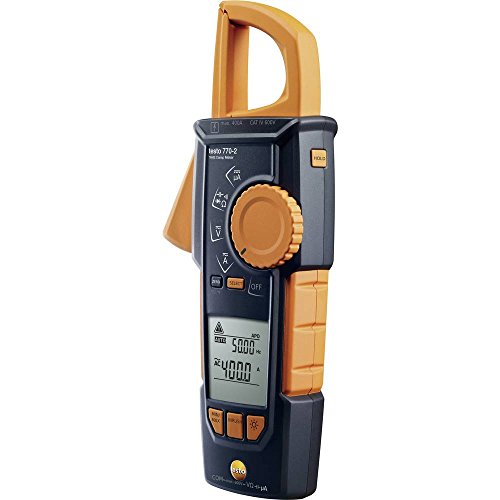
Testo 770-2 Clamp Meter Review: The Hook-Clamp That Decides the Job
A mechanism-first review of the Testo 770-2 hook-clamp meter, including what the listing states, what it omits, and where the hook design stops being the right answer.
Read More→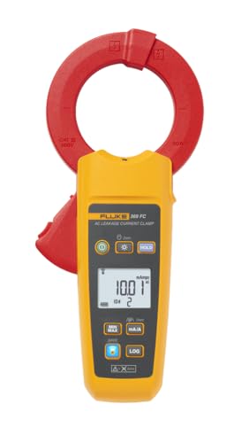
Fluke FLUKE-369 FC Leakage Current Clamp Meter Review: What the Listing Leaves Out
A source-led review of the Fluke 369 FC that highlights the unpublished specifications and their practical consequences.
Read More→
HiLetgo LCR-T4 Component Tester Review: The First Hour
A first-hour review of the HiLetgo LCR-T4 kit, covering what it measures, what the listing leaves out, and when a different instrument is the better answer.
Read More→