As an Amazon Associate, Akermin earns from qualifying purchases. Product links on this page are affiliate links.
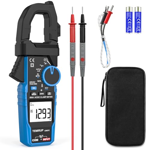
Short answer: For most HVAC and motor work, P1 is the pick because the listing puts the inrush function in the clamp jaw alongside non-contact voltage and a dual voltage and current display, so you can watch the running value while you capture the start. P5 and P9 are the same meter under two listings and both publish a 1000 A AC/DC range with a 100 ms inrush window that the listing says works above 10 A, which suits larger single and three phase motors. P2 is the value option: 1000 A, True RMS, VFD and LoZ modes, and an inrush function the listing explicitly restricts to AC. If you only work on domestic compressors and small pumps, P3, P6 and P12 publish a 600 A range that covers them, and P7 is the 1000 A version of the same family.
Why a starting surge is invisible to a normal clamp
A clamp meter works by measuring the magnetic field around a conductor. The jaw does not touch the wire, so there is no circuit to break and no burden voltage to disturb the load. That part is straightforward. The complication is what the meter does with the field it senses.
A general purpose clamp meter samples the field and averages it over a window chosen to give a stable display. That is exactly what you want when you are reading a steady running current. It is exactly what you do not want when the event you care about lasts a fraction of a second. A motor start produces a surge that rises almost instantly and then decays over a few cycles to a few hundred milliseconds. An averaging meter started before the motor and read after it will show you the running current and nothing else. The surge happened between two averages and left no trace on the display.
Inrush mode changes the sampling strategy. Instead of averaging, the meter watches for a peak over a short defined window and holds the highest value it sees. The window is the specification that matters, and it is the one most listings leave out. Where it is published, it is about 100 ms. That figure is not arbitrary. It is long enough to sit inside the decay of a typical motor start and short enough that the meter is not still holding a value after the motor has reached running speed. If you want the broader picture of what these instruments do outside the inrush function, the general clamp meter comparison covers the category.
What inrush current tells you about a motor
The inrush figure is a diagnostic, not a specification. A healthy motor draws a predictable surge on start, typically several times its running current, and then settles. When the surge is wrong, the shape of the wrongness points at the fault.
A surge that is far higher than expected, or one that does not decay, suggests the rotor is not turning freely. That is the locked rotor case, and it is the one that trips breakers and burns windings. A surge that is lower than expected can point at a supply problem, a failing capacitor on a single phase motor, or a start winding that is not being energised. A surge that is normal but followed by a running current that is too high points somewhere else entirely, often at a mechanical load or a failing bearing.
The reason to measure rather than guess is that the breaker trip curve and the motor protection are both sized around the start. If you only ever read running current, you are blind to the part of the cycle that actually stresses the protection. The listing for P5 is unusually useful here because it publishes a floor: the inrush function works well above 10 A. That tells you the meter is built for loads with a real surge, not for control circuits. For work on drive-fed motors specifically, the VFD clamp meter comparison goes into the filtering question in more detail.
The specification that matters most is the one nobody publishes
Read the listings on this page and a pattern emerges. Almost every meter claims True RMS, a count resolution, a maximum current and a list of functions. Very few publish the two numbers that decide whether the inrush function will actually work for you: the capture window and the minimum current at which the function triggers.
P2, P3, P5 and P7 publish the window as about 100 ms. P5 goes further and publishes the trigger floor. The others are silent. That silence is not necessarily a defect, but it means you cannot compare them on the specification that matters, and you should not assume they behave the same way. A meter with an unstated window might capture 20 ms or 500 ms; the first would miss a slow start, the second would hold a value that no longer reflects the surge.
The same logic applies to accuracy. None of these listings publish an accuracy figure for the inrush capture itself. That is normal for the category, and it is why the honest use of the function is comparative. Measure a motor you know is healthy, record the number, and then measure the suspect one. The difference between the two readings is the information. An absolute figure quoted to three digits would imply a precision the listing does not claim.
The maintenance nobody mentions
A clamp meter has no moving parts in the measurement path, which makes it feel maintenance free. The jaw is the exception. The mating faces of the jaw are part of the magnetic circuit, and anything that separates them changes the reading. Dust, paint, metal filings and a film of oil all introduce an air gap, and an air gap reduces the sensed field. A meter that reads low on every circuit is often a meter with dirty jaw faces.
The fix is simple: wipe the mating faces with a clean cloth and check that they close flush with no visible gap. Do this before you trust a low reading, and especially before you conclude that a motor is drawing less than it should.
The other maintenance item is the battery. Inrush mode is a peak capture, and a weak battery can cause the capture to behave erratically before the low battery indicator becomes obvious. If a reading looks wrong and the jaw is clean, replace the battery before you chase a fault that is not there. The test leads deserve the same attention: a cracked lead or a loose connector will affect every voltage reading, and the clamp jaw will tell you nothing about it.
Where the category stops being the right answer
An inrush clamp meter answers one question well: how much current did this load draw at the moment it started. It is a diagnostic instrument, and it is not an alarm, a recorder or a power quality analyser.
It is not an alarm. None of these meters will warn you that a motor is about to fail. They show a number when you are standing in front of the equipment. If you need continuous protection, that is a job for a motor protection relay or a thermal overload, not a handheld meter.
It is not a recorder. The capture window is about 100 ms on the meters that publish it. You get one number per start, not a waveform. If you need to see the shape of the surge, you need a recording instrument with a current probe, which is a different class of tool.
It is not a power quality analyser. True RMS tells you the heating equivalent of a distorted waveform, which is the right number for a motor. It does not tell you the harmonic content, the phase relationship or the power factor. For drive work, the filtering question is covered in the VFD measurement guide, and for DC motor checks the approach is different again, as set out in the DC motor clamp meter comparison. Knowing where a tool stops is as useful as knowing what it does.