As an Amazon Associate, Akermin earns from qualifying purchases. Product links on this page are affiliate links.
For a dedicated drive job, P1 is the pick because it is the only product here whose listing describes logging and trending of measurements and wireless transmission of results, which is what you need when a fault appears intermittently on a drive that is running. P4 is the value pick and the only one of the low-cost pair whose listing names a VFD mode alongside LoZ; P5 publishes nearly identical wording, which tells you the two are the same instrument under different names. P2 and P3 are not clamp meters for drive output work at all: P2 is a general purpose multimeter and P3 is a kit that converts a multimeter into a clamp meter with an AC-only jaw rated to 400 A. If your question is motor current on a drive, P1, P4 or P5 answer it. If your question is voltage at the drive terminals with a DMM, P2 and P3 belong to a different page.
Why a drive output breaks an ordinary clamp meter
A variable frequency drive does not put a sine wave on the motor cable. It switches a DC bus on and off thousands of times a second and varies the width of those pulses to synthesise a lower frequency. The motor winding averages that switching into something close to a sine wave because it is an inductor, but your clamp meter sits in the cable and sees the switching edges as well as the fundamental.
Two things go wrong. First, a meter that measures average and scales to RMS will under-read a distorted waveform, sometimes by a large margin, because the scaling factor it uses assumes a pure sine. That is why true RMS is not a marketing word on this job; it is the difference between a current reading you can act on and one you cannot. Second, the switching carrier, typically in the low kilohertz, may sit inside the meter’s bandwidth and be counted as signal. A meter with a low-pass filter or a dedicated drive mode strips the carrier out and reports the fundamental current the motor actually sees.
There is a third problem that is not about the meter at all. The output of a drive is pulse width modulated, and the voltage edges are steep. That stresses the insulation of anything you connect to it, and it stresses the input protection of the instrument. A meter rated CAT III 1000 V is rated for the transient environment you are standing in. The listings here that state a safety category state it for a reason.
What the listings actually publish, and what they leave out
The honest summary of this group is that the specification you need most, the bandwidth or the filter behaviour above the drive carrier, is barely published at all. Here is what each listing does say.
| Product | Current range stated | True RMS stated | VFD mode stated | Inrush stated | Safety category stated | Wireless or logging stated |
|---|---|---|---|---|---|---|
| P1 | 1000 A AC/DC | Yes | Not stated | Not stated | Not stated | Yes, Bluetooth app, log and trend |
| P2 | Not a clamp meter, DMM only | Yes | Not stated | Not stated | CAT III 1000 V, CAT IV 600 V | Not stated |
| P3 | 400 A AC via i400 clamp | Yes, on the 87V | Not stated | Not stated | Not stated for the kit | Not stated |
| P4 | 1000 A AC/DC | Yes, 6000 counts | Yes | About 100 ms, AC only | Not stated | Not stated |
| P5 | 1000 A AC/DC | Yes, 6000 counts | Yes | About 100 ms, AC only | Not stated | Not stated |
Read the P1 row carefully. The listing describes the 376 FC as a 1000 A AC/DC true RMS wireless clamp with an iFlex flexible current probe, and it describes logging and trending. It does not use the phrase VFD anywhere. That does not mean it cannot do the job; it means the listing does not make the claim, and you should not treat a missing claim as a claim. If a drive mode matters to you, ask before buying.
The P4 and P5 rows are the mirror image. Both publish a VFD mode and a LoZ mode explicitly, and both state 6000 counts. Neither publishes a safety category, a bandwidth figure, or a filter cutoff. The 100 millisecond inrush window is stated on both, and both listings carry the same caveat that inrush does not work on DC current. P4 and P5 are functionally the same instrument; the wording is too close for them to be anything else. Choose on availability.
The flexible probe question, and why P1 sits apart
A rigid jaw has to close around the conductor. In a drive cabinet the motor cable is often bundled, short, or routed where a jaw will not fit without pulling conductors apart, which is a bad idea on a live drive. A flexible current probe wraps around the conductor instead, and P1 is the only product in this group whose listing states that it includes one. That is a physical access advantage, not a measurement accuracy advantage, but on real drive terminations it is often the difference between taking a reading and not taking one.
The second thing P1’s listing states is wireless transmission of results and the ability to log and trend. On a drive fault that only appears under load or at a particular speed, a single reading at the panel tells you almost nothing. Logging lets the instrument sit on the conductor while the machine runs through its cycle, and you review the trend afterwards. That is a different working method from walking up with a clamp and reading a number.
What the listing does not state is the current range of the flexible probe separately from the 1000 A figure, nor a bandwidth. If you need to know the probe’s own accuracy at the carrier frequency, that is not published here.
The clamp meters and kits worth considering for drive work
Fluke 376 FC
The listing states 1000 A AC/DC true RMS measurement with a flexible current probe, plus Bluetooth transmission of results to a phone app and the ability to log and trend measurements to catch intermittent faults. That combination is what separates a drive troubleshooting tool from a general clamp: the fault you are chasing often is not present when you are standing at the panel.
Aicevoos Inrush Clamp Meter
The listing names a VFD mode and a LoZ mode in the same sentence, states 1000 A AC/DC and 6000 counts true RMS, and describes an inrush capture of about 100 milliseconds. It is the only budget entry here that publishes a VFD claim rather than leaving you to infer it from the bandwidth.
AstroAI Inrush Clamp Meter
The published specifications match P4 almost word for word, including the 1000 A AC/DC rating, the 6000 counts, the 100 millisecond inrush window and the VFD and LoZ wording. Treat the two as one instrument and choose on which one you can actually get.
When the answer is a multimeter, not a clamp
Two of the products supplied for this topic are not clamp meters and should not be presented as if they were. P2 is a Fluke 87V MAX, a rugged true RMS digital multimeter rated IP67 and CAT III 1000 V and CAT IV 600 V, with an 800 hour battery figure stated and a built-in thermometer. It is an excellent instrument for measuring voltage, and for drive work a true RMS DMM is exactly what you want on the input side of the drive and on the control terminals. It has no jaw. It cannot measure motor current without a separate current clamp.
P3 is that separate clamp, bundled. The listing describes a Fluke 87V multimeter with an i400 AC current clamp that converts it into a clamp meter for AC current up to 400 A, plus a temperature probe, test leads and alligator clips. Note the limits the listing itself states: the i400 is AC only, and 400 A. If your drive runs a motor above 400 A, or if you need to measure DC current anywhere in the circuit, this kit does not do it. It is a good general industrial kit; it is not a drive current instrument in the sense the P1, P4 and P5 listings are.
For the voltage side of drive work specifically, a dedicated DMM page is the better place to look. See multimeters for VFD troubleshooting for that comparison, and clamp meters with inrush if motor starting current is your main question rather than running current.
LoZ, ghost voltage and the live-dead check on a drive
Both P4 and P5 publish a LoZ mode, and on a drive this matters more than it sounds. A high impedance voltmeter can read a phantom voltage on a conductor that is not actually connected to a source, because it picks up capacitive coupling from adjacent live conductors. In a cabinet full of switching cables that phantom reading is common and it is dangerous, because it can make a dead conductor look live or, worse, train you to distrust the meter. LoZ mode puts a low impedance across the input, which pulls the phantom voltage down to near zero while leaving a real supply voltage essentially unchanged. It is the standard way to confirm a circuit is actually live or actually dead.
The listing for P4 states the LoZ function eliminates ghost voltages and interference and calls it practical for detecting whether a power source is live. P5 states the same thing in the same words. Neither listing gives the input impedance of the LoZ mode, which would tell you how much it loads the circuit. On control circuits with sensitive electronics, a low impedance mode can disturb what it is measuring, so use it on the power side, not on signal wiring.
Note also that neither listing states a safety category. On a drive cabinet that is a real gap. If you are working on the line side of a drive, you want a stated CAT rating, and here only P2 publishes one.
The number that is not on any of these listings
Bandwidth is the specification that decides whether a clamp meter reads the fundamental motor current or the drive carrier as well. None of the five listings publishes a bandwidth figure. None publishes a low-pass filter cutoff. Two of them publish the words VFD mode without saying what the mode does to the signal. That is the central limitation of choosing from listings alone, and it is worth saying plainly rather than dressing up.
What you can do is reason from what is stated. A true RMS meter with a published VFD mode is more likely to have been designed with the carrier in mind than one with no such claim. A meter with a stated safety category has been type tested to a published standard. A meter with a flexible probe and logging lets you work around the access and intermittency problems that no specification fixes. Pick the combination that matches the failure you are actually chasing.
For a broader view of the category, including meters that publish different trade-offs, see general clamp meters and three phase clamp meters. If your work is on the DC side of a drive or a solar inverter, the requirements change again and clamp meters for DC motor checks is the closer match.
Recommended Tools


Products shown because their documented specifications fit this guide. Price and availability are on Amazon and can change.
Frequently Asked Questions
Do I need a true RMS clamp meter for a VFD?
Yes. A drive output is a switched waveform, not a sine wave, and an averaging meter scales its reading using a factor that only holds for a sine. On distorted waveforms the reading drifts low, sometimes badly. Every product in this group that is a clamp meter publishes true RMS, so this is not a differentiator here; it is a floor.
Which of these actually has a VFD mode?
P4 and P5 both state a VFD mode in their listings, alongside a LoZ mode. P1 does not use the term. That does not prove P1 cannot measure on a drive, but the listing does not make the claim, and you should not assume a feature that is not published.
Can I measure DC current on a drive with these?
P1, P4 and P5 all state 1000 A AC/DC current, so DC current measurement is published for those three. P3's i400 clamp is stated as AC only, up to 400 A. Also note that both P4 and P5 state their inrush function is AC only and will not work on DC current.
Is the inrush function the same as a VFD mode?
No, and the listings separate them. Inrush captures a short burst of starting current, stated as about 100 milliseconds on P4 and P5, and helps you spot a motor or starting circuit problem. A VFD mode is about reading steady running current correctly on a switched waveform. You may want both, but they answer different questions.
Why is no safety category stated for most of these?
The listings simply do not publish one. Only P2 states CAT III 1000 V and CAT IV 600 V. On a drive cabinet, where transient overvoltages are a real hazard, a missing category is a genuine gap and worth asking the seller about before you rely on the instrument on the line side.
P4 and P5 look identical. Which should I buy?
The published specifications match closely enough that they are the same instrument under two names: 1000 A AC/DC, 6000 counts, VFD and LoZ modes, 100 millisecond inrush, same caveats. Choose on availability and on which listing you can actually verify, not on a difference in the numbers.
Affiliate disclosure: Akermin earns a commission from qualifying Amazon purchases made through links on this page. Our editorial picks are based on documented specifications and owner feedback, not commissions.
Related Guides

Fluke 1AC II VoltAlert Review: Two Detection Thresholds in One Listing
A pocket sized non contact voltage tester whose tip glows red and beeper sounds when voltage is detected, with a continuous self test and a choice of audible or silent operation.
Read More→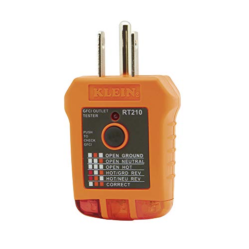
Klein Tools RT210 Review: A Fault Finder That Does Not List Its Faults
A three wire receptacle tester for standard and GFCI North American outlets, specified for 110 to 125 volts AC at 50 or 60 Hz, a 6.6 foot drop and an operating range of 32 to 140 degrees Fahrenheit.
Read More→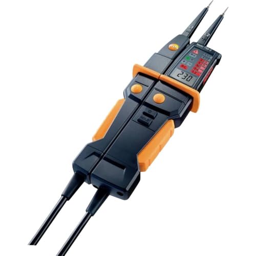
Testo 750-3 Review: Four Bullets, and No Published Category Rating
A two pole voltage tester with a three digit LCD showing measured voltage, a patented LED voltage bar viewable from any angle, polarity detection on DC and a GFCI test function for AC outlets.
Read More→