As an Amazon Associate, Akermin earns from qualifying purchases. Product links on this page are affiliate links.
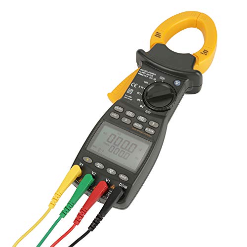
Short answer: For most three phase troubleshooting where you need power, power factor, and phase balance in one handheld, P1 (BTMETER 580P) and P9 (Kethvoz 580P) are the closest matches, both offering 9999 count true RMS measurement with three phase power functions. P2 (Fluke 378FC) is the strongest choice when non contact voltage detection and flexible current probes matter for safety and access. P4 (Extech PQ2071) suits balanced three phase power analysis with data logging. P6 (Hioki CM3286-50) adds harmonic monitoring to the 30th order. P5 (Vanlison) is a phase rotation tester, not a clamp meter, and should be chosen only if rotation and sequence are your sole concern. P12 (ETCR5000) is a full power quality analyzer for waveform capture and transient work, not a handheld clamp.
What three phase measurement actually requires
A single phase clamp meter measures one conductor. A three phase clamp meter has to do more: measure three conductors in sequence, compare them, and in many cases compute power from the relationship between voltage and current on each phase. The instrument you choose determines whether that comparison is a routine task or a series of separate measurements stitched together in a notebook.
The core measurement is current per phase. Clamp each conductor in turn and record the reading. If the three readings are close to equal, the load is balanced. If one phase carries significantly more current than the others, the load is unbalanced, and the neutral may be carrying current it was not sized for. This is the single most common three phase fault you will find with a clamp meter, and it requires nothing more than a true RMS current measurement and the discipline to check all three phases.
Power measurement adds a layer. True power in watts is not simply voltage multiplied by current; it is voltage multiplied by current multiplied by the cosine of the phase angle between them. That phase angle is why power factor matters. A meter that measures phase angle, such as P1 or P4, lets you calculate power factor from first principles rather than trusting a computed display. For load studies and energy audits, that distinction matters. If you are new to clamp meters generally, the best clamp meters guide covers the single phase fundamentals.
Phase balance and the sequence measurement workflow
Phase balance is a comparison, not a single reading. The practical workflow is to clamp L1, note the current, clamp L2, note the current, clamp L3, note the current, then compare. A meter with a dual display, such as P1, lets you hold two values at once so you can read current and frequency together or power and power factor together. That reduces the number of times you cycle through the display and the number of chances to misread a value.
Phase sequence is a separate question. It asks whether L1, L2, L3 are in the correct order. Motors rotate in the direction determined by sequence, so confirming it before connection prevents reverse rotation. P1, P5, and P6 state phase sequence or phase rotation functions. P5 does it without contacting conductors, which is the safety advantage in energized panels, but it does not measure current or power. If you need both sequence and power, you need a meter that does both, or two instruments.
The mistake to avoid is assuming that a balanced current reading means the system is healthy. Balanced current with high harmonic distortion still overheats transformers and neutrals. That is why harmonic analysis, available on P6 up to the 30th order and on P12 up to the 50th order, matters for modern installations with variable frequency drives and switch mode power supplies. For drive specific work, see clamp meters for VFD measurements.
Crowded panels and the case for flexible probes
A rigid clamp jaw needs a clear loop of conductor to close around. In a crowded panel, that loop may not exist. Conductors are bundled, busbars are close together, and the space between them is measured in millimetres. A flexible current probe solves this by threading through gaps that a jaw cannot enter. P2 includes an iFlex flexible probe; P5 uses 20 inch clamps for reach. Most other meters in this group do not state a flexible option.
Jaw size is the other access specification. P4 states a jaw that accommodates conductors up to 2.16 inches (55 mm). That is a published figure and it matters, because a jaw that will not close around your conductor is useless regardless of its accuracy. Many listings in this class do not publish jaw size at all, which is why the table marks it as not stated. If you are buying for a specific installation, measure the conductor or busbar first and confirm the jaw capacity from the full datasheet.
The maintenance nobody mentions is the jaw mating surface. A clamp meter measures current by sensing the magnetic field around the conductor, and the jaw forms a magnetic circuit. Dirt, rust, or a poor mating surface between the jaw faces introduces an air gap, which changes the reading. Wipe the jaw faces clean before a critical measurement. This is not in most manuals, but it is the most common cause of a clamp meter reading low. For flexible probe options specifically, see clamp meters with flexible current probes.
Where a clamp meter stops being the right answer
A clamp meter is a spot measurement instrument. It tells you what is happening now, at the point where you clamped it. It does not record a waveform, it does not capture a transient, and it does not tell you what happened three hours ago when the breaker tripped. When the question is not what is happening now but what happened, you need a different class of instrument.
P12 is a power quality analyzer, not a clamp meter. It displays voltage and current waveforms on four channels each, measures harmonics up to the 50th order, captures transients, and stores up to 150 transient waveforms. It monitors inrush and start-up currents with rise and fall curves. That is the instrument you reach for when a clamp meter has told you the current is normal but the breaker still trips. It is also the instrument you reach for when you need to prove what happened during a fault, not just what the system looks like when it is running normally.
A single gas detector does not satisfy confined space entry, and a clamp meter does not satisfy power quality investigation. The two are different jobs. If your work is routine maintenance, load checking, and phase balance, a handheld three phase clamp meter such as P1, P4, or P6 is the right tool. If your work is diagnosing intermittent faults, harmonic problems, or transient events, you need an analyzer. For related electrical diagnostic tools, see electrical fault finders.
Specifications to confirm before you buy
The listings in this group vary widely in what they publish. P4 states plus or minus 2 percent accuracy on up to 1000 A AC and a 55 mm jaw. P1 states a 9999 count display but not the accuracy class. P2, P3, P6, and P7 do not publish accuracy or jaw size at all. That is not a reason to avoid them, but it is a reason to request the full datasheet before purchase if accuracy matters for your work.
CAT rating is the safety specification that determines what installation category the meter is rated for. P11 states CAT III 1500 V, which is a solar specific rating. P10 states CAT IV 600 V. Most others in this group do not state a CAT rating in the listing. If you are working on industrial three phase systems, confirm the CAT rating matches the installation category you are working in. A meter without a stated CAT rating should not be assumed to have one.
True RMS is stated or implied by most of these meters, and it matters for any load that is not a pure sine wave. A averaging meter reads the peak of a distorted waveform and scales it as if it were a sine wave, which gives a reading that is too low. True RMS measures the heating effect of the waveform directly. For three phase work with drives, rectifiers, or switch mode supplies, true RMS is not optional. The best multimeters guide covers true RMS in more detail for general electrical work.