As an Amazon Associate, Akermin earns from qualifying purchases. Product links on this page are affiliate links.

VEYFIY · VEYFIY Portable Solar Panel Tester with Photovoltaic Multimeter and Watt Meter, 20A 60V ABS Housing for Field Efficiency Measurement(200W)
View on AmazonPrice and availability are shown on Amazon and can change at any time.
A handheld photovoltaic tester in an ABS housing that reads the maximum power point, the open circuit voltage and the short circuit current of a panel on an LCD, rated for 20 A and 60 V, supplied with a clip for attaching directly to the panel. Three figures on the page do not reconcile. Twenty amps at sixty volts is twelve hundred watts, and the title carries two hundred. On an instrument you connect to a photovoltaic source, the voltage figure is a safety limit, and 60 V is the smallest ceiling in this whole category.
Twenty amps times sixty volts is not two hundred watts
The title states 20A 60V, and then, in brackets at the end, 200W. The arithmetic takes a second: twenty amps at sixty volts is twelve hundred watts, six times the bracketed figure.
There are three readings available, and the listing supports none of them over the others:
- 200 W is the real ceiling. The 20 A and 60 V figures would then be component ratings that can never be reached together, which is normal engineering, and the instrument would be limited to small panels.
- 200 W is a model designation. Variants of the same instrument are often distinguished by a number in the title that is not an electrical limit. In that case 20 A and 60 V govern.
- It is an error. Given the rest of the wording on this page, discussed below, this cannot be dismissed.
Those three outcomes are very different for a buyer. A current residential or commercial module is commonly several hundred watts, so if 200 W binds, this instrument cannot measure a single modern panel. If it does not bind, the voltage figure still restricts you to one panel at a time. Either way the answer determines whether the tool fits the array you own, and the page does not give it.
This is the kind of discrepancy that is easy to wave away as sloppy copy. It should not be waved away, because the figures in question are the ones that decide what you may safely connect.
Sixty volts is one panel, and only when it is warm
The voltage ceiling on a photovoltaic instrument is not like the voltage range on a mains multimeter, for one reason that changes everything: you cannot turn the source off. An array is live whenever light falls on it. There is no isolator that makes the conductors safe to work on, only switches that disconnect what is downstream.
So the headroom between the instrument rating and the worst case source voltage has to be real, and the worst case is not the nameplate figure.
Open circuit voltage is the highest voltage a module produces, measured with nothing drawing current from it. Datasheets quote it at a cell temperature of 25 C, and it has a negative temperature coefficient, meaning it rises as the cells get colder. A cold, bright winter morning is the condition that produces the highest voltage a system will ever see, because irradiance is high and cell temperature is low, and a few tenths of a percent per degree below the reference adds up quickly.
Set that against 60 V. Many single modules carry a nameplate open circuit voltage in the forties, which on paper looks comfortable and in cold conditions is not comfortable at all. Two modules in series exceed the rating without any weather help whatsoever. Our explainers on measuring open circuit voltage and the gap between open circuit and operating voltage cover the arithmetic.
The honest description of this instrument is therefore a single panel tester for low voltage modules, and the listing should say that in those words rather than leaving a buyer to work out that 60 V excludes every string.
Force where the listing means power
The first bullet reads: accurately measure output force at Maximum Force Point (Pmax). The third refers to a photovoltaic module force tester. Two bullets use insuring where they mean ensuring.
Force is a physical quantity measured in newtons. Power is measured in watts. Pmax, the abbreviation the listing itself puts in brackets, is the maximum power point, the place on a panel current voltage curve where the product of current and voltage is largest. There is no reading under which force is the right word.
It is tempting to treat this as pedantry about translation. It is not, for a specific reason: on a measuring instrument the terminology is the specification. The three quantities this tool reports, maximum power point, open circuit voltage and short circuit current, are distinguished from their near neighbours entirely by precise naming. Open circuit voltage is not operating voltage. Short circuit current is not operating current. Maximum power is not rated power.
A page that cannot keep power and force apart gives you no basis for believing it has kept those pairs apart, either in its description or in the firmware behind it. And the distinctions are the whole product.
What survives this criticism is the choice of measurements. Pmax, Voc and Isc are exactly the right three to read off a panel, because together they let you compare what a module is doing against what its label says it should do. The selection is sound. It is the published account of it that cannot be relied on. Our guide on choosing a photovoltaic tester sets out what else to look for.
A clip is not an MC4 connector
The last bullet promises a quick connection setup with a battery clip, a secure clamp for direct attachment to panels so you can start measurements immediately without complex configurations.
Panels do not present anything a crocodile clip can grip. They terminate in MC4 connectors, a moulded keyed pair designed so that a mated joint is sealed and an unmated one is touch safe, because the conductors behind them are energised in daylight and nobody can switch them off. That is the standard the whole industry builds to.
A clip needs bare metal. In practice that means one of three things: an adapter lead with MC4 on one end and bare conductors on the other, which the listing does not say is included, a junction box terminal, or improvising on an exposed conductor, which is the option to avoid. The difference between plugging a tester into a string and improvising a connection to it is the difference between a five second measurement and a job with a risk assessment.
The second bullet adds a related puzzle. It describes field use without bulky equipment or extra batteries. Read literally, that suggests the instrument powers itself from the panel under test. The listing never states a power source either way, and the distinction has a practical edge: an instrument that borrows power from the panel cannot tell you anything about a panel producing nothing, which is one of the two situations that make you reach for a tester in the first place.
Everything the bullets quantify, which is two numbers
| Item | Listing statement |
|---|---|
| Measurements | Maximum power point, open circuit voltage, short circuit current |
| Current rating | 20 A |
| Voltage rating | 60 V |
| Power figure in the title | 200 W, not reconciled with 20 A at 60 V |
| Display | LCD, described as high contrast |
| Housing | ABS |
| Connection | Clip for direct attachment to a panel |
| Accuracy of any measurement | Not stated in the listing bullets |
| Resolution | Not stated in the listing bullets |
| Which power ceiling applies | Not stated in the listing bullets |
| Power source of the instrument | Not stated in the listing bullets |
| MC4 leads supplied | Not stated in the listing bullets |
| Stored readings or export | Not stated in the listing bullets |
| Display digits | Not stated in the listing bullets |
| Operating temperature range | Not stated in the listing bullets |
| Isolation or category rating | Not stated in the listing bullets |
| Dimensions and mass | Not stated in the listing bullets |
The absence of any accuracy figure is the largest gap in the table, and it undoes the stated purpose. A tester exists so you can decide whether a panel is producing what its label promises, and that is a comparison between two tolerances: the panel one, which is on the datasheet, and the instrument one, which is nowhere. A reading a few percent below nameplate therefore cannot be attributed.
It is worth separating what is absent from what is unstated, though. There is no claim of curve tracing here, no irradiance sensor and no temperature measurement, and the listing does not pretend otherwise. That is a point in its favour. It also sets a hard limit on what the readings mean, because without irradiance and cell temperature no measurement can be corrected to standard test conditions. The instrument can tell you a panel is roughly in line with its neighbours. It cannot tell you a panel is within its warranty tolerance.
The one job this can honestly do
There is a real use here. If you have a small low voltage system built from individual modules, the kind of thing on a shed, a boat, a van or an off grid cabin, well inside 60 V and under whichever power ceiling turns out to be real, this will find the panel that has failed. Measure each module in turn under the same sky, within a few minutes of each other, and the one that is out of step is the one to investigate. Comparison does not need an accuracy figure or a correction to standard conditions, because both panels experienced the same conditions and the instrument error is common to both readings.
That is the whole honest recommendation, and it is narrower than the listing suggests. Do not plan on using it on a roof mounted string, on anything with modules in series, or on work where a number goes into a report someone else relies on. And do not connect it to an array at all until the manufacturer states, in writing, which of the two power figures is the real limit. On a source that is energised whenever the sun is up, a ceiling the listing contradicts itself about is not a specification question to settle afterwards.
Recommended Tools
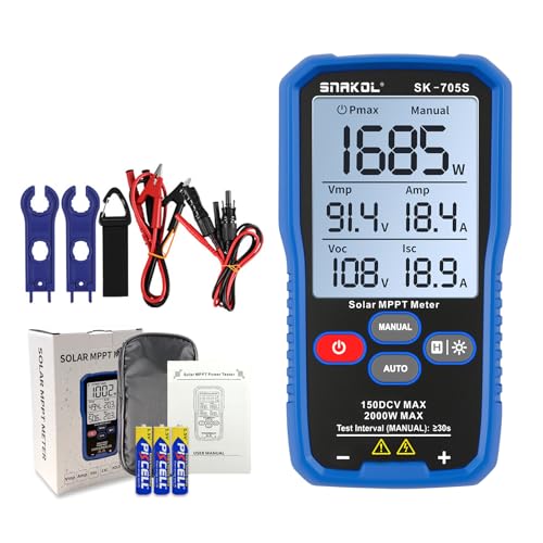


Products shown because their documented specifications fit this guide. Price and availability are on Amazon and can change.
Frequently Asked Questions
Which is the real ceiling, 200 W or 1200 W?
The listing does not resolve it and a buyer cannot. Twenty amps at sixty volts is twelve hundred watts, so the 200 W in the title is either a tested power limit well inside the component ratings, a model designation that means nothing electrically, or an error. Each reading points somewhere different. If 200 W binds, the instrument cannot measure a single current residential module, most of which are far above that. If it does not bind, the 60 V figure still limits you to one panel. Get it in writing before connecting anything.
Why is 60 V such a low ceiling for a solar tester?
Because a single modern module can approach it on its own. Open circuit voltage is the highest voltage a panel produces, it is specified at a cell temperature of 25 C, and it rises as cells get colder. On a cold bright morning a module sits well below that reference temperature and its open circuit voltage climbs above the nameplate figure by a few tenths of a percent per degree. A module with a nameplate open circuit voltage in the forties therefore leaves far less margin against a 60 V instrument than the two numbers suggest, and two modules in series exceed it outright.
What does Maximum Force Point mean?
Nothing. The abbreviation in brackets beside it, Pmax, is the maximum power point, the operating point on a panel current voltage curve where the product of current and voltage is greatest. Force is a different physical quantity measured in entirely different units. The listing uses force where it means power at least three times, and uses insuring where it means ensuring twice more, which reads as a translation that has not been checked by anyone who knows the subject.
Can I connect this to a panel without an adapter?
The listing describes a secure clamp for direct attachment, called a battery clip, and mentions no MC4 leads. Panels terminate in MC4 connectors, which are keyed, latching and touch safe, so that a connected lead never exposes a live conductor. A crocodile clip has to grip something bare, which on a photovoltaic circuit means either an adapter lead, a junction box terminal, or improvising on a source that is live in daylight. Confirm what is in the box before planning a job around it.
Does this instrument trace an I-V curve?
No, and to its credit it does not claim to. It reads the maximum power point, the open circuit voltage and the short circuit current, which are three points rather than a curve. Those three numbers tell you whether a panel is performing. A curve tracer sweeps the whole load range and plots the relationship, and the shape of that plot is what distinguishes shading from series resistance from uniform degradation. This instrument tells you something is wrong without telling you what.
What does the lack of any accuracy figure cost me?
The entire comparison the instrument exists to make. A tester is used to decide whether a measured output is within tolerance of a nameplate figure, and that decision needs the instrument tolerance alongside the panel tolerance. With no accuracy published for any of the three measurements, a reading five percent below nameplate cannot be attributed to the panel or to the meter. The use that survives this is comparing panels against each other under the same sky, where a shared instrument error cancels out.
Affiliate disclosure: Akermin earns a commission from qualifying Amazon purchases made through links on this page. Our editorial picks are based on documented specifications and owner feedback, not commissions.