Best Continuity Testers: 9 Simple, Reliable Picks for Fast Circuit Checks
Continuity is the simplest electrical test and one of the most used: is there an unbroken path from here to there. This hub compares nine instruments that state a continuity function, explains what the beep really means, and separates the tools that merely indicate a path from those that measure its resistance.
As an Amazon Associate, Akermin earns from qualifying purchases. Product links on this page are affiliate links.
Our Top Picks
Tools were compared on whether the listing states a continuity function, what else the instrument measures, and whether it reports a resistance value or only an audible indication. Every figure comes from the manufacturer listing; we ran no tests of our own.
Best Overall
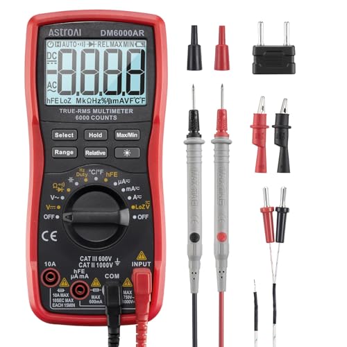
AstroAI True RMS 6000 Counts Digital Multimeter
Continuity alongside nine other measurements in an auto-ranging meter.
Listing states continuity plus AC and DC current and voltage, capacitance, frequency, duty cycle, resistance, diode and temperature
None of these listings publishes the resistance threshold at which its continuity buzzer sounds, so that column is absent rather than filled with estimates. Thresholds differ substantially between meters, which is why a beep alone is not a measure of connection quality.
How to Choose a Continuity Tester
Four things to weigh:
Beep or Number
A buzzer confirms a path exists. A resistance reading tells you whether it is a good one. Seven of the nine here show a value; the phone set and the PV tester do not state one.
How Far Apart the Ends Are
Bench and panel work needs one meter. A cable between two floors needs either very long leads or a two-handset set such as the Loop Check phones.
Circuit Must Be Dead
Continuity testing injects a small current from the instrument. On a live circuit the reading is meaningless and the meter may be damaged. Isolate, prove dead, then test.
What Else You Need
Almost every general meter and clamp includes continuity, so the real decision is which other functions you want in the same body: current, capacitance, insulation or PV testing.
It means the resistance between the probes is below a threshold chosen by the manufacturer, usually somewhere between 10 and 50 ohms. It does not mean the connection is good. A corroded joint reading 15 ohms will beep on many meters and still fail under load. If the quality of the connection matters, read the resistance value rather than listening for the tone.
Can I test continuity on a live circuit?
No. The test works by sending a small current out of the meter and measuring what comes back, and a live circuit swamps that with its own voltage. The reading is meaningless, the meter can be damaged, and on a higher-energy circuit the situation is dangerous. Isolate the circuit, prove it dead with a voltage tester, discharge any capacitance, then test.
Why does my meter beep on everything?
Usually because the probes are touching something they should not, the component under test is in parallel with another path through the circuit, or the meter is set to a resistance range rather than the dedicated continuity position. Components in circuit are the most common cause: a resistor, coil or another branch provides a low-resistance path around the item you think you are testing. Isolate one end of the component before judging it.
Do I need a dedicated continuity tester?
Almost never. Seven of the nine products here are multimeters or clamp meters where continuity is one function among many, and any of them does the job. The exceptions are specialised: a two-handset phone set for long runs between two people, and a PV tester for the continuity test that forms part of a solar commissioning sequence.
What is the difference between continuity and a low resistance test?
Scale and purpose. Continuity answers yes or no at the tens of ohms level. A low resistance or bonding test measures down into the milliohms, with a defined test current, to confirm that a protective conductor can carry fault current safely. A continuity buzzer will happily pass a bonding conductor that a proper low resistance test would fail.
Reviews
AstroAI True RMS 6000 Counts Digital Multimeter Best Overall
Nobody buys a dedicated continuity tester any more, and this meter is the reason why. AstroAI lists continuity as one function among ten, alongside AC and DC voltage and current, capacitance, frequency, duty cycle, resistance, diode testing and temperature, with true RMS and 6000 counts on an auto-ranging display.
That combination matters for continuity work specifically because the same instrument gives you the resistance value. A beep tells you there is a path. The number tells you whether that path is 0.3 ohms, which is a good connection, or 8 ohms, which is a corroded one that will beep happily and then fail under load. Being able to switch between the two in one movement is worth more than any dedicated tester.
The listing does not state the continuity threshold, which is the resistance below which the buzzer sounds, and that figure varies widely between meters. It also states no category rating. True RMS and 6000 counts are useful, but for a continuity check neither is doing any work, so this pick is about breadth rather than precision.
Strengths
Continuity plus nine other stated functions
Shows the resistance value, not just a beep
Auto-ranging and true RMS
Priced as a general-purpose meter, not a specialist tool
Loop Check Phones Continuity Test Electrician Phone Set ES001-NB Best for Long Runs
Checking continuity on a bench is trivial. Checking it across a 200 metre run between a riser cupboard and a plant room, with no phone signal in either, is not, and it is the job this product exists for. The set is two handsets that connect to opposite ends of the conductors under test, confirming the path and letting the technicians at each end speak to each other over the same pair.
That second function is what makes it worth its price. Identifying which of twenty conductors in a multicore is which requires coordination, and coordination without communication means walking the building repeatedly. A pair of handsets turns a half-day of cable identification into an hour.
The listing is unusually thin, giving little beyond the product identity, so no operating voltage, no maximum cable length, no battery type and no resistance threshold can be quoted. It is also a single-purpose tool with no measurement capability at all: it will not give you a resistance value, and it has no place in fuse or component testing.
The continuity check you actually perform is the one where the tool is in your pocket. This ALLOSUN meter is built around that idea: a 3 3/4 digit auto-ranging pocket meter that the listing describes as covering DC and AC voltage and current, non-contact voltage detection, resistance, capacitance and frequency.
Auto-ranging matters more on a small meter than a large one, because a pocket instrument has a cramped dial and fewer positions. Not having to select a resistance range keeps the continuity check to one movement, and the non-contact function gives you a live screening tool in the same body.
The usual caution about very cheap meters applies. The listing states no category rating, no accuracy, no continuity threshold and no true RMS. A 3 3/4 digit display is around 4000 counts, which is adequate but not generous. Treat it as a convenient second meter for low-energy work rather than the instrument you take to a panel.
Strengths
Fits a pocket, so it is actually present when needed
Short answer: the AstroAI true RMS 6000 count multimeter is the sensible buy, because continuity is one of ten stated functions and it shows the resistance value rather than only beeping; the Loop Check Phones ES001-NB set is the specialist tool for long runs, giving two technicians a handset each and voice communication over the conductors under test; and the ALLOSUN pocket meter is the value pick, an auto-ranging 3 3/4 digit meter with continuity, NCV and capacitance that actually fits in a pocket.
What continuity testing is, and what it is not
A continuity test sends a small current from the instrument through whatever is between the probes and reports whether it comes back. A path means a low resistance; no path means an open circuit. Every multimeter and most clamp meters include the function, usually with a buzzer so the result can be heard while you watch the probes instead of the screen. What the test is not is a measurement of connection quality. The buzzer threshold is a manufacturer’s choice, typically somewhere in the tens of ohms, and none of the nine listings here publishes theirs. A joint that has corroded to 15 ohms will beep confidently on many meters and then drop most of the supply voltage as soon as load current flows. What continuity is and why meters beep explains the mechanism.
Read the number, not just the tone
The single habit that makes continuity testing useful is switching from the buzzer to the resistance display whenever the answer matters. A short length of conductor should read close to the resistance of the leads themselves, a few tenths of an ohm. A switch contact should read essentially zero when closed. A winding reads whatever the manufacturer specifies. Anything reading several ohms where it should read a fraction of one is a finding, and the beep hides it. Seven of the nine products here display a resistance value: the AstroAI, the ALLOSUN, the DEASOMIYE with its stated 60 megohm resistance range, the BTMETER clamp and the two Klein clamps. Start by nulling the leads: touch the probes together, note the reading, and subtract it.
Dead circuits only
Continuity is a powered test from the meter’s point of view, which is precisely why it cannot be performed on a live circuit. The supply voltage overwhelms the test current, the reading is nonsense, and depending on the meter and the energy available the instrument can be damaged or destroyed. The sequence is always the same: isolate, prove dead with a separate voltage tester, discharge any stored energy in capacitors or long cable runs, then test. How to measure resistance safely covers the procedure, and the voltage tester hub covers proving dead.
Parallel paths, the reason honest components fail the test
The most common confusing result in continuity work is a beep where there should not be one. In an assembled circuit, the component between your probes is rarely the only path between those two points. A coil, a resistor, another branch of the wiring or a bleed path through a board all provide a route for the test current, and the meter reports the parallel combination. The fix is to lift one end of the component under test, or to isolate the section of wiring, before drawing conclusions. This is also why continuity results taken on an installed multicore cable need one end disconnected at the far end before they mean anything.
The two-ended problem and the phone set
Testing a cable that runs between two rooms, two floors or two buildings is a different problem from testing a component on a bench, and it is why the Loop Check Phones set exists. Two handsets, one at each end, confirm the path and let the technicians talk over the conductors being tested. On a multicore where twenty cores have to be identified and labelled, that removes the need for one person to walk the route after every check. The alternative approaches are a very long test lead, which is impractical beyond a few tens of metres, or shorting pairs at one end and inferring identities from the pattern at the other, which works but is slow and error prone.
Continuity as part of a formal test sequence
Two entries here treat continuity as one step in a documented procedure rather than a casual check. The Kyoritsu KEW 6010B is a multifunction installation tester whose listing states continuity alongside insulation, loop and RCD testing, designed to IEC 61010-1 and IEC 61557. The HT Instruments PV-ISOTEST states 1500 V PV insulation and continuity testing with a ground fault locator function, which is the continuity test used on a solar array’s equipotential bonding and string conductors as part of an IEC 62446-1 Category 1 commissioning sequence. In both cases the continuity result has to be recorded with a value, not a beep, which is why these instruments belong to a different class from a pocket meter. See the multifunction tester hub and PV commissioning testers.
When continuity is not enough
For protective bonding conductors, earthing conductors and any connection that must carry fault current, a continuity buzzer is not an adequate test. The relevant measurement is a low resistance test in the milliohm region, performed with a defined test current so the result reflects behaviour under load rather than the behaviour of a trickle. A conductor that beeps and reads 2 ohms might still be a failed bond. Milliohm meters for low resistance testing covers the instruments that do this properly, and how to test continuity with a multimeter covers the everyday version.
Products were compared on whether the listing states a continuity function, whether the instrument reports a resistance value, and what else each listing claims to measure. No manufacturer here publishes the continuity buzzer threshold, so none is quoted. Owner feedback was reviewed for repeated reports of lead failure and unreliable buzzers. We ran no laboratory tests and publish no measurements of our own.
A circuit tracer works by injecting a signal onto a conductor and detecting the resulting field with a receiver, so its usefulness depends on the signal path and the wiring topology.
A plain explanation of where energy monitor accuracy comes from, how to read the specifications, and the cases where a whole-home monitor is the wrong instrument.
A practical explanation of why outlet testers fail to light, misread, or mislead, and how to tell whether the fault is in the tool, the outlet, or the circuit.