As an Amazon Associate, Akermin earns from qualifying purchases. Product links on this page are affiliate links.

ZIBOO · ZIBOO 393 True RMS Clamp Meter, 1000A AC/DC Current Auto-Ranging Digital Multimeter, 1700V DC High Voltage for Solar/PV, Inrush Current, VFD, LOZ, NCV, Measures Temp/Capacitance/Resistance
View on AmazonPrice and availability are shown on Amazon and can change at any time.
A 6000 count true RMS clamp meter reading up to 1000 A on both AC and DC, with inrush capture, a variable frequency drive mode, low impedance voltage measurement, non contact voltage detection, resistance, capacitance, frequency, temperature and a CAT III 1000 V and CAT IV 600 V safety rating. It is a well specified instrument with one serious problem: the page gives three different maximum DC voltages, and the highest appears in the product name while the lowest is the safety rating.
Three voltage ceilings on one page
Lay the three statements side by side.
- The product name: 1700V DC high voltage, for solar and photovoltaic use.
- The second bullet: safely measures DC voltage up to 1500V, and AC voltage up to 1000V.
- The fifth bullet: rated at CAT III 1000 V and CAT IV 600 V.
Those cannot all be describing the same instrument honestly. The gap between the first two is 200 V of unexplained headroom on the number a buyer searches for. The gap between the second and third is more serious, because a measurement category rating is not a marketing figure, it is the voltage at which the instrument was qualified to survive the transients of its working environment.
Why this matters more here than on a bench meter comes down to the nature of the circuit. A photovoltaic array has no off switch. In daylight the string sits at its open circuit voltage whether anyone is working on it or not, and that voltage rises as cell temperature falls, so the worst case is a cold bright morning rather than a hot afternoon. System designs are built around 1000 V and 1500 V tiers precisely because the ceiling has to be known.
The position this site takes on a conflict like this is the same one it has taken before. A voltage ceiling on a source that cannot be isolated is a safety limit, not a specification to be optimistic about, so this instrument cannot be recommended for high voltage string work until the figure is resolved in writing by the manufacturer. For comparison with instruments whose rating is unambiguous, see our list of meters rated for 1500 V photovoltaic systems.
What a CAT III 1000 V rating actually bounds
Measurement categories get quoted as though they were quality grades. They are not; they are statements about location and the transient energy found there.
The category describes where the instrument belongs. CAT IV covers the origin of an installation, the service entrance and the supply side, where a surge arrives with the full energy of the network behind it. CAT III covers distribution within a building, boards and fixed wiring. The voltage paired with it is the working voltage at which that transient withstand was verified.
So CAT III 1000 V and CAT IV 600 V is a respectable and normal pairing for an industrial clamp meter, and it is the right rating to look for on panel work. What it does not do is authorise a measurement above 1000 V working. The rating stops where it stops.
There is a further wrinkle specific to solar. The category system was written around AC mains distribution, and large photovoltaic arrays present something different: a sustained DC voltage much higher than the AC systems the categories were framed for, with its own fault behaviour. That is why instruments genuinely built for this work state a DC working voltage explicitly alongside their category rating rather than leaving the reader to reconcile two numbers. Our explainer on what a CAT rating means goes through the energy levels behind each category.
Zero the jaw before you believe a DC current reading
The first bullet mentions a Zero or REL function and calls it essential for clearing magnetic hysteresis before taking accurate DC current measurements. That is both true and more interesting than it sounds.
Reading DC current with a clamp requires a Hall effect element in the magnetic circuit of the jaw, because the transformer principle that handles AC produces nothing from a steady current. The iron in that circuit retains a little magnetisation after it has been around a live conductor, and the element reports that residual field as though it were current.
The consequence is an offset. Open the jaw with no conductor in it and the display may sit a little above or below zero, and that error then adds to or subtracts from every reading until it is cleared. Because it is a fixed quantity in amps rather than a percentage, it matters least on a large current and most on a small one.
That makes it directly relevant to solar work. A string in early morning light, a trickle into a battery, a standby draw: those are the readings where an uncleared offset turns a plausible number into a misleading one. The function is on the instrument and the listing tells you why to use it, which is better than most pages manage.
Inrush, VFD and low impedance solve three different problems
The third bullet groups them as pro level diagnostic features. They are, but they are unrelated to each other, and each exists because an ordinary meter gives a confident wrong answer in one specific situation.
- Inrush. A motor starting draws a surge several times its running current for a fraction of a second. A normal display averages over a window long enough to miss it entirely, so the instrument has to be told to capture the first moment after the current appears. This is how you find out whether a motor that trips its protection is drawing an abnormal start or whether the protection is simply too tight.
- VFD mode. A variable frequency drive output is not a sine wave; it is a rapidly switched waveform whose average approximates one. A true RMS input measures what is actually there, including the switching, so the reading is high and unstable. The mode filters the high frequency content so the figure reflects what the motor sees.
- Low impedance. A long cable run beside a live one picks up voltage by capacitive coupling, and a high impedance meter draws so little current that this ghost voltage reads as though the conductor were live. A low impedance input loads the circuit enough for a coupled voltage to collapse while a genuine supply holds up.
Add non contact voltage detection with an indicator, a backlit display and a built in flashlight, and the working package is thorough. The clamp meters with inrush capture page covers how much the implementation varies between instruments.
Six thousand counts is resolution, not accuracy
| Specification | Published in the listing |
|---|---|
| Current | 1000 A AC and DC, true RMS, auto ranging |
| Display counts | 6000 |
| DC voltage | 1700 V in the product name, 1500 V in the bullets |
| AC voltage | 1000 V |
| Safety rating | CAT III 1000 V, CAT IV 600 V |
| Resistance | Up to 60 megohms |
| Capacitance | Up to 6000 microfarads |
| Frequency | Up to 20 MHz |
| Temperature | Up to 1000 C, stated as 1832 F |
| Special modes | Inrush, VFD, LoZ, NCV, live wire test, diode and continuity, max and min |
| Zero function | REL, for DC current offset |
| Accuracy, any function | Not stated in the listing bullets |
| Jaw opening size | Not stated in the listing bullets |
| Temperature probe type | Not stated in the listing bullets |
| Battery type and runtime | Not stated in the listing bullets |
| Data logging or connectivity | Not stated in the listing bullets |
| Ingress protection or drop rating | Not stated in the listing bullets |
Counts and accuracy get conflated constantly, so it is worth separating them. 6000 counts describes how finely the screen can divide a range: on a 600 V range the smallest step it can display is 0.1 V. That is a property of the display, and a meter can show a figure to that resolution while being wrong by several percent.
Accuracy is the separate figure, normally written as a percentage of the reading plus a number of least significant digits, and it is absent for every function on this page. Ranges are published generously, tolerances not at all, so nothing measured with this instrument can be quoted with an uncertainty attached.
The missing jaw opening is the other practical blank. A 1000 A rating implies conductors of a size that may not fit a small jaw, and on busbars and large feeders the opening decides whether the instrument can be used at all.
Resolve the voltage rating before it goes near a string
As a general purpose industrial clamp meter for work within its safety rating, this is a strong specification. 1000 A on both AC and DC, true RMS, a DC zero function with an explanation attached, inrush, drive filtering and low impedance voltage, plus the usual resistance, capacitance, frequency and temperature functions. For panel and motor work on systems at or below 1000 V, the feature set is what a technician would choose.
For the application the product name is advertising, high voltage photovoltaic, nobody should buy it until the DC voltage ceiling is stated as one number and that number is reconciled with the category rating. An array is energised whenever the sun is up, its voltage rises in the cold, and the consequence of an under rated instrument on a high voltage string is not a wrong reading. Ask the manufacturer in writing, and if the answer does not arrive, buy an instrument whose own page agrees with itself.
Recommended Tools
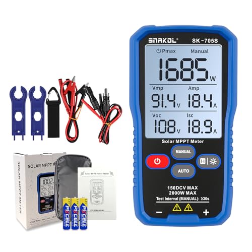

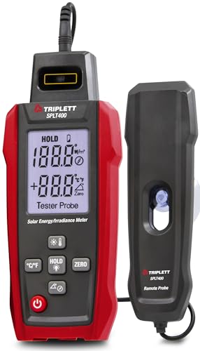
Products shown because their documented specifications fit this guide. Price and availability are on Amazon and can change.
Frequently Asked Questions
What is the actual maximum DC voltage?
The listing does not establish one. The product name leads with 1700V DC high voltage for solar and photovoltaic use, the second bullet states the meter safely measures DC voltage up to 1500V, and the fifth bullet gives the safety rating as CAT III 1000 V and CAT IV 600 V. Those are three different figures describing the same limit. Until the manufacturer resolves it in writing, this instrument cannot be recommended for work on high voltage strings, because that figure is a safety boundary rather than a feature.
Does a CAT III 1000 V rating allow a 1500 V measurement?
No, and this is the heart of the problem. A measurement category rating is a pair: the category describes where in an installation the instrument is designed to be used, and the voltage is the working voltage at which it was qualified to survive the transients expected there. CAT III 1000 V means qualified at 1000 V working. It does not describe behaviour at 1500 V, and it certainly does not describe behaviour at 1700 V.
Why does a DC clamp need a zero function?
Because the jaw is a magnetic circuit and iron remembers. After the jaw has been closed around a current carrying conductor, a small residual magnetisation remains, and the Hall effect element reads that as a current when there is none. The Zero or REL function subtracts the residual before you take the reading. The error is a fixed offset in amps, so it matters most on small currents, which is exactly the case when checking a string in weak light or a standby load.
What do the inrush, VFD and LoZ modes each solve?
Three separate problems. Inrush captures the brief surge when a motor starts, which can be several times running current and is gone before an averaging display settles. VFD mode filters the high frequency switching of a drive output so the reading reflects the fundamental rather than the carrier. LoZ presents a low input impedance so capacitively coupled voltage on a disconnected conductor collapses instead of appearing as a live reading. Each one exists because a normal meter gives a confidently wrong answer in that situation.
Does the listing publish any accuracy figures?
No. It publishes ranges, which is a different thing: 60 megohms of resistance, 6000 microfarads of capacitance, 20 MHz of frequency and temperature to 1000 C. It also publishes 6000 counts, which is display resolution, the finest step the screen can show. Accuracy would be stated as a percentage of reading plus a number of digits, and no such figure appears for any function.
Affiliate disclosure: Akermin earns a commission from qualifying Amazon purchases made through links on this page. Our editorial picks are based on documented specifications and owner feedback, not commissions.
Related Guides

UNI-T UT503PV Review: A DC 1000 V Headline on a CAT III 600 V Body
A solar insulation resistance tester that works on energised PV strings up to DC 1000 V, with test voltages of 125, 250, 500 and 1000 V, a range to 4000 megohms, automatic discharge, 1000 stored result sets and USB or Bluetooth transfer.
Read More→
ANCEL BA101 Review: The Exclusion List Is the Most Useful Bullet
A 12 volt battery, cranking and charging system tester covering 100 to 2000 CCA that reports state of health, state of charge, voltage, current and CCA, drawing its own power from the battery under test.
Read More→
Tenmars Solar Power Meter Review: One Accuracy Figure, Two Very Different Jobs
A handheld solar irradiance meter reading 0 to 1999 watts per square metre or 0 to 634 BTU per square foot per hour, with a selectable 199.9 or 1999 scale, maximum and minimum tracking, data hold and manual zeroing.
Read More→