As an Amazon Associate, Akermin earns from qualifying purchases. Product links on this page are affiliate links.
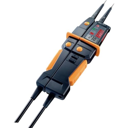
Testo · Testo 750-3 (0590 7503) Voltage Tester w/ 3-Digit LCD, GFCI Testing
View on AmazonPrice and availability are shown on Amazon and can change at any time.
A two pole voltage tester with four published features: GFCI testing on AC outlets, a three digit LCD showing the measured voltage, a patented LED voltage bar designed to be read from any angle, and polarity detection on DC. The combination of digits and a bar is a real advantage in a working panel. The problem is what four bullets leave out on an instrument held against live conductors, which includes the measurement category, the voltage ceiling and any reference to a standard.
Three digits and a bar are two instruments in one
Two pole testers have traditionally been indicators. A row of neons or LEDs lights progressively, and you read the result as a band: something is live, and it is in the region of one nominal level rather than another.
That is enough for the commonest question, which is whether a conductor is energised. It is not enough for the second commonest, which is whether the voltage is where it ought to be. A circuit reading well below its nominal level under load is telling you about a resistive joint, an undersized conductor over a long run or a neutral that is not doing its job, and no band display can show you that.
A numeric readout can. The second bullet promises a three digit LCD displaying actual voltage measurements, which is the difference between knowing a socket is live and knowing it is sitting noticeably low with the kettle on.
Keeping the LED bar alongside it is the sensible decision rather than a redundancy. The bar is faster, it works when you cannot see the screen, and it survives being glanced at from across a cupboard. Digits take longer to read and demand a line of sight. An instrument that offers both lets you use the appropriate one, and on live work the appropriate one is usually the fast one.
All round viewable is not a cosmetic claim
The third bullet describes a patented all-around viewable LED voltage bar indication, and this is easy to dismiss as packaging language. It is not.
Think about where a two pole tester is actually used. Both hands are occupied holding probes. The instrument body ends up wherever the probes allow, which in a consumer unit, a distribution board or a junction box often means angled away from you, half behind a bundle of conductors, or down near the floor while you are standing. A display readable only from directly in front is a display you cannot see at the moment the probes are in contact.
The alternatives are both bad. You let go of a probe to reposition the instrument, or you take the reading from memory after withdrawing. On a live circuit neither is acceptable practice.
Indication visible from any direction removes the problem. It is one of those specifications that sounds like styling until you have been in the position it addresses, and it is a reasonable thing to hold a patent on.
Tripping a residual device from the probe tips
The first bullet is a function, not a feature: the tester performs GFCI tests on AC outlets.
The mechanism is worth understanding because it governs what the result means. A ground fault circuit interrupter watches for an imbalance between the current flowing out on the line conductor and the current returning on the neutral. Any difference implies current leaving through a third path, which in a fault is a person or an enclosure. The tester creates a small, deliberate imbalance by diverting current to the earth connection, and a working device should open.
What you have demonstrated at that point is that the protective device operates. That is genuinely valuable and it is the check that gets skipped most often. What you have not demonstrated is that it operated inside its rated disconnection time, or that it needed no more than its rated residual current to do so. A device that trips sluggishly, or only at well above its rating, still trips. Establishing either figure needs an instrument that ramps current and measures the interval before the circuit opens, which is a different class of tool and is covered in our roundup of RCD testers.
Being able to perform the check from the probes you are already holding, without a separate adaptor, is a sensible piece of integration. Just do not mistake a trip for a verified trip time.
Polarity detection, and what it is for
The fourth bullet gives polarity detection for DC measurements, and it is the quietest useful item on the list.
On alternating current the question does not arise. On direct current it arises constantly and the stakes are higher, because reversing a connection on a battery bank, a control circuit or a photovoltaic string can destroy something rather than merely produce a wrong figure. Reading a minus sign on a small display while both hands are committed and your head is at an angle is exactly the moment errors happen. An explicit polarity indication removes the interpretation step.
The bullets do not say over what DC span the detection or the measurement works, which matters for anyone intending to use it on photovoltaic wiring, where open circuit string voltages run far above anything found in a domestic AC installation.
The specification an instrument for live work has to publish
| Specification | In the four bullets |
|---|---|
| Display | Three digit LCD showing measured voltage |
| Secondary indication | Patented LED voltage bar, viewable all round |
| GFCI test | Yes, on AC outlets |
| DC polarity | Detected and indicated |
| Measurement category | Not stated in the listing bullets |
| Maximum working voltage | Not stated in the listing bullets |
| AC and DC measuring spans | Not stated in the listing bullets |
| Tolerance on the displayed figure | Not stated in the listing bullets |
| Frequency span | Not stated in the listing bullets |
| Low impedance input | Not stated in the listing bullets |
| Continuity or phase rotation functions | Not stated in the listing bullets |
| Probe tip guarding and exposed tip length | Not stated in the listing bullets |
| Ingress protection and drop rating | Not stated in the listing bullets |
| Behaviour with flat or absent batteries | Not stated in the listing bullets |
| Product safety standard | Not stated in the listing bullets |
The first two blanks are the ones that should stop a buyer. A measurement category is not a quality grade, it is a statement about the transient overvoltage the instrument is designed to withstand, and the available energy behind a fault rises the closer you work to the incoming supply. A tester rated for socket outlet work is the wrong instrument at an origin, and nothing on this page tells you which this is. The explainer on CAT II, CAT III and CAT IV ratings goes through what each category covers.
The low impedance row deserves attention too. A tester whose job includes proving a conductor dead has to deal with voltage induced onto an idle conductor by a live one running beside it. A high impedance input will display that induced voltage, which looks like a live circuit and is not; a low impedance input loads it away. Which behaviour this has is unpublished, and the consequences are set out in our note on why ghost voltage appears on a multimeter.
Settle the rating in writing before it touches a circuit
The design decisions in these four bullets are good ones. Digits and a bar together, visibility from any angle, a protective device check from the probe tips, and unambiguous polarity on DC add up to a tester built by people who have used one in a confined space. For verifying outlets, confirming presence and absence of voltage, and sanity checking a level rather than a band, it covers the ground.
The reservation is not about what it does but about what has not been published. A voltage tester is one of the few instruments deliberately applied to energised conductors, so its category rating and voltage ceiling are safety limits rather than specifications, and they should be on the page where the purchase is made. Get both confirmed in writing, along with whether the input is low impedance, and match them against the installations you work on before this goes anywhere near a live circuit.
Recommended Tools


Products shown because their documented specifications fit this guide. Price and availability are on Amazon and can change.
Frequently Asked Questions
Why does a three digit display matter on a voltage tester?
Because a band is not a number. An indicator only tester tells you that voltage is present and roughly which nominal level it belongs to. A numeric readout lets you see that a circuit sits noticeably below where it should, which is how volt drop under load, a poor connection and a shared or floating neutral announce themselves. Having both a bar and digits means you can glance for presence and read the figure only when the figure matters.
What does the GFCI function actually prove?
That the protective device responds. A tester of this kind diverts a small current through the earth path so that a residual current device sees an imbalance and opens. That confirms the mechanism moves, which is worth knowing and is not nothing. It does not establish that the device opened within its rated time or at its rated current, because neither quantity is measured. Those require an instrument that ramps the current and times the interruption.
Is a measurement category rating really necessary?
Yes, on anything applied to live conductors. A category describes the transient overvoltage environment the instrument is built to survive, not just the steady voltage it can read, because the energy available behind a fault increases as you move closer to the incoming supply. A tester perfectly safe at a socket outlet can be the wrong tool at a distribution board. Four bullets with no category and no voltage ceiling leaves that question open.
What is polarity detection on DC for?
It tells you which probe is sitting on the positive conductor, rather than leaving you to interpret a minus sign while holding two probes in an awkward position. It is useful on photovoltaic strings, control circuits, battery wiring and anywhere a reversal causes damage rather than merely a wrong reading. The bullets state the function and do not state the DC span over which it works.
Will it tell me a conductor is genuinely dead?
That depends on a property the listing does not publish: whether the input presents a low impedance. A high impedance instrument can display a voltage induced onto a disconnected conductor running alongside a live one, which reads as dangerous when it is not, and a tester can also be fooled in the other direction by a poor reference. A low impedance input loads the circuit enough to collapse an induced voltage. Nothing in these four bullets addresses it.
Affiliate disclosure: Akermin earns a commission from qualifying Amazon purchases made through links on this page. Our editorial picks are based on documented specifications and owner feedback, not commissions.
Related Guides

Fluke 1AC II VoltAlert Review: Two Detection Thresholds in One Listing
A pocket sized non contact voltage tester whose tip glows red and beeper sounds when voltage is detected, with a continuous self test and a choice of audible or silent operation.
Read More→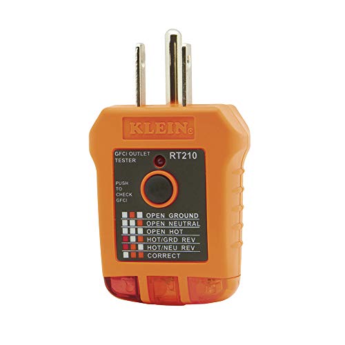
Klein Tools RT210 Review: A Fault Finder That Does Not List Its Faults
A three wire receptacle tester for standard and GFCI North American outlets, specified for 110 to 125 volts AC at 50 or 60 Hz, a 6.6 foot drop and an operating range of 32 to 140 degrees Fahrenheit.
Read More→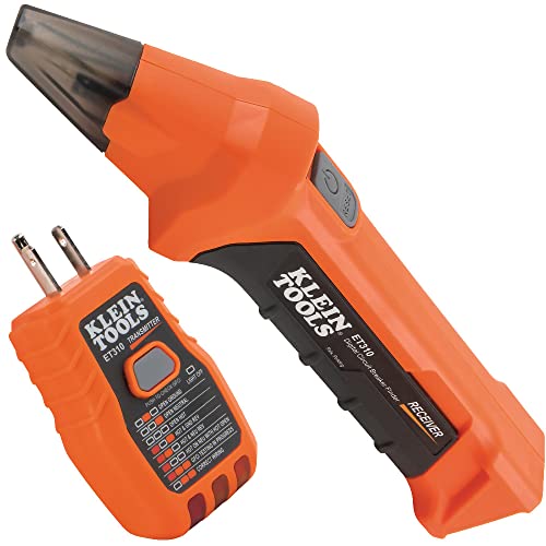
Klein Tools ET310 Review: Wide Compatibility Means 90 to 120 Volts
A two part circuit breaker finder with a transmitter that connects at the outlet or fixture and a receiver that scans the panel, stated to work on 90 to 120 V AC circuits and carrying a built in GFCI test function.
Read More→